A model-based adaptive non-null interferometry (MANI) is proposed for steep optical freeform surfaces in situ testing. The deformable mirror (DM) affording the flexible compensation is monitored with the beam in the interferometer by a wavefront sensor. The residual wavefront aberration in the non-null interferogram is eliminated by the multi-configuration ray tracing algorithm based on the system model, especially the DM surface model. The final figure error can be extracted together with the surface misalignment aberration correction. Experiments proving the feasibility of the MANI are shown.
The freeform optical element has been widely used in illumination[1], displays[2], and imaging systems[3,4] due to its high performance in beam shaping and aberration correction. Nevertheless, the metrology approach has not yet kept pace in the past few years and, thus, limits the application of freeform optics[5]. The best choice for the precision optical surfaces test is non-contact metrology led by various interferometry, which has elegant performance in modern optical testing, such as spherical and aspherical surfaces tests[6]. However, it is powerless for the freeform surfaces test because of the difficulty of non-rotational symmetric wavefront aberrations compensation in a traditional interferometer, even in a subaperture stitching interferometer[7–9]. Most of null[10,11] and non-null[12,13] compensators designed for aspherical surfaces interferometry are not suitable for the freeform surfaces test because the wavefront produced from them is usually rotationally symmetric. The specially designed compensator, such as a computer generated hologram (CGH), is needed, but the flexibility is thus reduced greatly[14,15]. Therefore, a flexible compensator for non-rotational symmetric wavefront aberrations is urgently desired. In recent years, the deformable mirror (DM) started coming into researchers’ sight due to its high performance in flexible aberration correcting. In 2004, Pruss and Tiziani[16] made effort to employ a membrane DM as the reflective compensator to realize the alterable Zernike defocus compensation for the flexible aspheric surfaces test. This attempt inspired the flexible test for freeform surfaces. But, the surface figure accuracy of the DM hindered its further application in interferometry. In 2014, Fuerschbach et al.[17] made the null test for an polynomial mirror with the assist of a DM. However, the DM surface was measured by the Zygo interferometer in advance, and, thus, the final accuracy would be reduced due to the instability of the DM surface. It was not applied for the in situ test. In 2016, Huang et al. proposed an adaptive null interferometric method for in situ freeform surfaces metrology[18], in which a deflectometry system was employed for real time DM deformation monitoring. But, this method would suffer the sophisticated calibration and unsatisfactory precision of the auxiliary deflectometry system. Moreover, these null tests would be helpless in steep freeform surface tests, because the commercially available DMs now have limited strokes on the order of 40 μm maximum, depending on the aberration type (except for tip/tilt stroke). Therefore, the null test for a steep freeform surface is difficult to realize, except when more rigorous null optics is designed to assist.
In this Letter, a model-based adaptive non-null interferometry (MANI) is proposed for steep optical freeform surface in situ metrology. The DM and the partial null lens (PNL)[12,13] in the non-null interferometer afford only partial aberration compensation according to the nominal shape decomposition of the tested surface in pursuit of distinguishable interferograms. The DM surface is monitored by the wavefront sensor in real time in the interferometer without other assisting monitoring systems, such as the deflectometry system. The residual aberrations in the resulted interferograms are treated by a model-based multi-configuration ray tracing (MCRT) algorithm for retrace error and misalignment elimination. In this way, the in situ flexible test for a steep freeform surface would be realized.
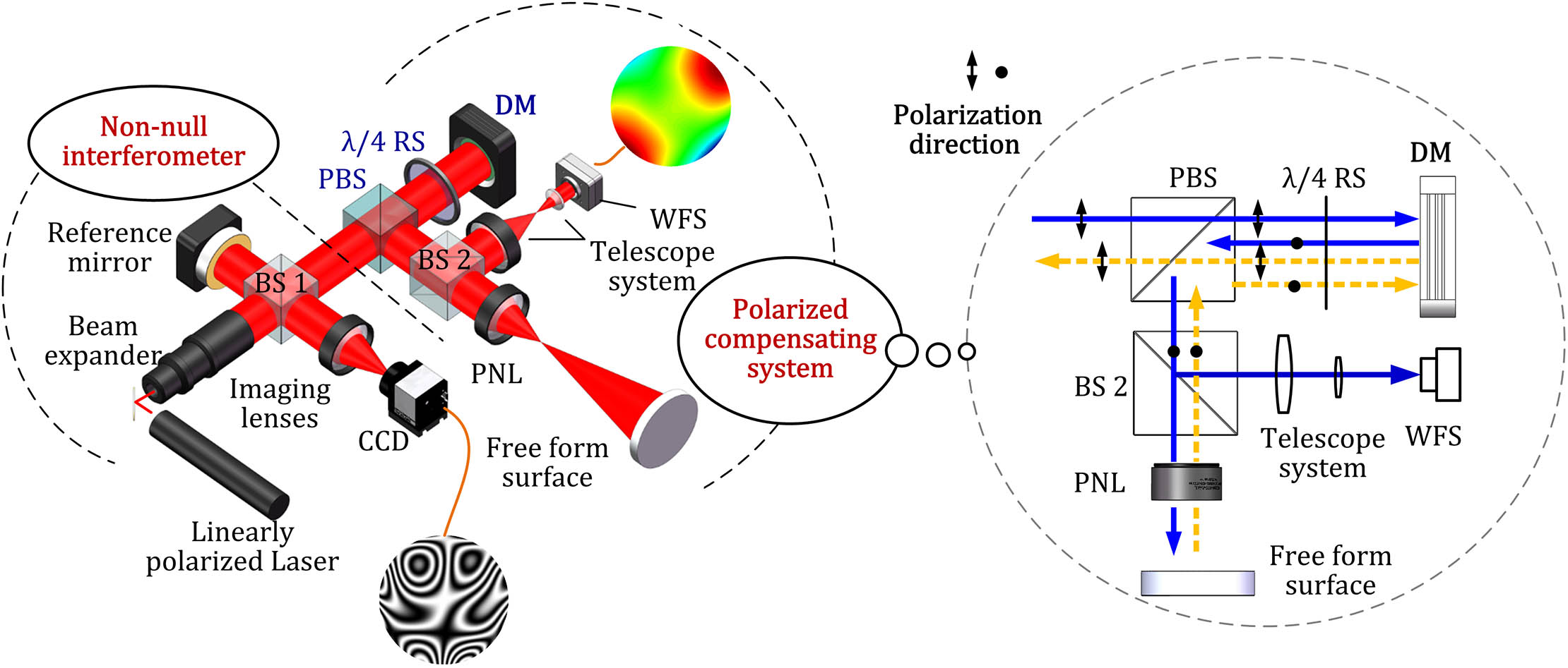
Figure 1 illustrates the MANI system layout. As shown in Fig. 1, the MANI system consists of the non-null interferometer and the polarized compensating system. The non-null interferometer is a basic Twyman–Green interferometer, which employs a linearly polarized laser. The beam transmitted from the non-null interferometer passes through the polarized compensating system. The reflected beam from the polarized compensating system returns to the non-null interferometer as the test beam. The test beam interference interferes with the reference beam reflected by the reference mirror at the beam splitter (BS1), and the resulted interferogram is imaged at the CCD by the imaging lens. The detail of the polarized compensating system is illustrated in the right of Fig. 1, in which the linearly polarized beam from the non-null interferometer travels through a polarized BS (PBS) and a retardation sheet (RS) and then arrives at the DM. The DM would provide the flexible non-rational symmetric aberrations compensation. After being reflected by the DM, the beam travels through the RS again, where the RS is oriented to rotate the polarization direction of the beam by 90°. The resulted linearly polarized beam would not pass through the PBS, and, thus, all will be reflected to BS2. BS2 (95% transmittance) divides the beam into two parts. The reflected one arrives at a wavefront sensor (WFS) after traveling through the telescope system; the transmitted one arrives at the tested freeform surface after traveling through the PNL. The reflected beam (the yellow arrow) by the tested surface would backtrack and be reflected by the DM again. The polarized direction of the resulted beam arriving at the PBS would rotate by 90° once again due to another round-trip traveling through the RS. Therefore, the beam would travel through the PBS and return to the non-null interferometer as the test beam. The non-null interferogram is thus obtained. Note that the WFS can measure the aberrations afforded by the DM, and, thus, the DM surface model can be set up accurately. The PNL is a simple design with a single lens and is easily modeled as well. The remaining task is to extract the figure error from the non-null interferogram and then map it to the nominal surface. This is a difficult issue in the non-null configuration because of the error couple of the surface misalignment aberrations and the figure error. An MCRT algorithm is proposed for this issue. Unlike the ray tracing method in non-null aspheric interferometry in our previous work[19–22], the multi-configuration is produced by the different DM deformations. For the known nominal surface, the test wavefront in the experiment can be expressed by an implicit function as where , , , , and are the freeform surface figure error, DM surface figure error, misalignment aberrations of the tested surface, misalignment aberrations of the DM surface, and other system error, respectively. would be calibrated before the experiment, and can be calibrated in case of no deformation (as a flat). Note that cannot be measured directly and would be extracted by the ray tracing with its reflective wavefront aberrations at the WFS. However, the calibration for surface misalignment error is a great challenge due to the six-degree freedom. That is to say, there are two unknown variables and in Eq. (1). We modified Eq. (1) such as
Sign up for Chinese Optics Letters TOC. Get the latest issue of Chinese Optics Letters delivered right to you!Sign up now
Figure 1.System layout and principle of the flexible MANI.
Although the DM surface deformation can be obtained by the WFS in real time, and would not be solved out with the single equation [Eq. (2)]. Therefore, multiple equations are needed. In the non-null configuration, can be changed quantificationally to structure multiple equations. Of course, the changed aberration is measured by the WFS in real time. Each change would result in a new test configuration, which has a little difference in . Note that different would introduce into the system different misalignment aberrations with the same surface misalignment . Thus, the th test would be characterized by in which .
A theoretical multi-configuration model is set up in the ray tracing program according to each test configuration in the actual experiment system, in which each configuration corresponds to each experimental measurement. Equation (3) in the multi-model would be expressed as where , , , and are the simulated counterparts in the model corresponding to Eq. (3), respectively. Of course, the values of are equal to their counterparts . By subtracting Eq. (4) from Eq. (3), we obtain
Because of the orthogonality of Zernike polynomials,
Thus, the quadratic sum of both sides of Eq. (5) for M measurements is obtained as where is the total measurement number. We obtain
A closed feedback system is set up to change the simulated surface figure error () and surface misalignment in the ray tracing program, making all the simulated test wavefronts () simultaneously approach the actual one () in the experiment. If all of the simulated test wavefronts () are close enough to the experimental ones () with approximating to , the surface figure error in simulation () would be able to characterize the actual one ().
The experiment system layout is presented in Fig. 2. The tested surface is a bi-conic mirror based on an aspheric base (aperture 50 mm, conic coefficient , conic coefficient , radius 201 mm, and radius 200 mm). The nominal sag of the bi-conic surface can be mainly decomposed into the Zernike defocus and astigmatism. The Alpao™ DM88 is employed with a maximum 30 μm defocus or astigmatism compensation at 25 mm aperture. The WFS employed is the Shack–Hartmann WFS with about 50 μm dynamic range for defocus or astigmatism.
The system model was set up in the ray tracing program according to the element parameters and initial measured interval parameters. Note that the MCRT algorithm is based on the system model, and, thus, the model should be calibrated to be consistent with the experiment system. The non-null interferometer model calibration would be carried out by ray tracing and error storage. The most important is the DM surface misalignment calibration. The tilt of the DM was easily aligned by wavefront aberration estimation in the case of a flat surface (no deformation). Subsequently, a defocus deformation of the DM was provided, and the DM surface decentration can be also calibrated by the tested wavefront evaluation. The DM in the experiment would be aligned until the coma coefficients of the wavefront at a WFS less than a threshold value (such as . Then, the DM in model was aligned until the coma coefficients of the tested wavefront equal 1 in the experiment. Now, we consider that the decentration of the DM surface in the experiment was little and had the same value as the one in the model. The next step was the DM axial position determination. A series of defocus deformations of DM would address this issue. The principle is like the MCRT algorithm. The MCRT algorithm based on the multi-configuration model was employed for this calibration, in which the multiple defocus deformations of the DM acted as the constraint, while the DM axial position () acted as the variable. When all of the simulated test wavefronts were close enough to the experimental ones, the DM axial position () in simulation would be consistent with the actual one (). Now, the DM calibration was complete. In fact, this method had been applied in our previous work[21] for simultaneous determination of aspheric curvature radius and axial position. The experiment proved that the calibration accuracy achieved more than 0.02%.
With a matched transmission sphere, the resulting interferogram was obtained and illustrated in Fig. 3(a), which was beyond the test range of the interferometer. A simple PNL (single lens) with F/2.5 was designed to partly compensate the defocus of the tested surface. The designed PNL can cover about 40 μm rotational symmetric departure, while the Alpao™ DM88 can cover a maximum 30 μm non-rotational symmetric departure from the best fit sphere. The resulted interferogram after defocus compensation is illustrated in Fig. 3(b) with regional indistinguishable fringes. Then, the DM provided the aberration compensation [about 17 μm peak-to-valley (PV) astigmatism, 6 μm defocus, and 4 μm spherical aberration], which is the approximate compensation extremity of the DM88 employed. The resulted interferogram is illustrated in Fig. 3(c), which shows that null fringe is unavailable.
Figure 3.Aberration compensation of the tested surface. (a) The optimal interferogram by transmission sphere, (b) the interferogram compensated by PNL in the experiment, and (c) the interferogram compensated by DM in the experiment.
Then, two were provided in the experiment in preparation for the MCRT algorithm. All three were extracted from the aberration measured by the WFS by ray tracing, as are shown in Fig. 4(a). , , and are astigmatism with other different aberrations. All three resulted interferograms after DM compensation are shown in Fig. 4(b) as well.
Figure 4.(a) The three DM surface figures and (b) the corresponding interferograms after DM compensation in the experiment.
The DM in the model provided the same compensation as the experiment. The resulted interferograms in the model are shown in Fig. 5(a). Compared with the three interferograms in Fig. 4(b), it is obvious that the tested surface in the experiment has misalignment with the one in the model. The MCRT algorithm was then carried out in the three-configuration model for the misalignment and figure error extraction. After the MCRT algorithm, the resulting interferograms in the model were changed and presented in Fig. 5(b), which have the same profiles with those in the experiment, as shown in Fig. 4(b). It implies the consistency of the position and posture of the test surface between the model and experiment after the MCRT algorithm operation. The final map of surface figure error was extracted and shown in Fig. 5(c). It was concluded from these results that the MCRT algorithm provided the accurate calibration for the surface misalignment error () accompanied by surface figure error extraction. Meanwhile, the tested surface was accurately mapped to the nominal function of the tested surface, as is shown in Fig. 5(c).
Figure 5.Result of MCRT algorithm. (a) The initial interferograms after DM compensation in the system model, (b) the interferograms after the MCRT algorithm in the system model, and (c) the map of surface figure error.
For the more powerful cross validation, we also measured a paraboloidal mirror in the MANI and Zygo interferometer. The tested surface has a 52 mm aperture and about 41 μm departure from its vertical spherical surface. The DM was employed for Zernike defocus compensation (μ). Figure 6(a) refers to the initial interferogram in the experiment, while Fig. 6(b) shows the interferogram after DM compensation. The MCRT algorithm was executed with in the form of Zernike defocus. Five were provided in the experiment and model. After the MCRT algorithm, the resulted interferogram in the model is presented in Fig. 6(c). The test surface figure error was extracted and presented in Fig. 6(d) with a cross validation result shown in Fig. 6(e), which is the result in the Zygo interferometer by the aberration-free method. Figure 6(f) is the direct difference map characterizing the testing error. The PV and rms value of the error are and , which proved the validity of the MANI.
Figure 6.Test results of the paraboloidal surface, where (a) is the initial interferogram in the experiment, (b) is the interferogram after DM compensation in the experiment, (c) is the interferogram in the model after compensation and the MCRT algorithm, (d) is the surface figure error map in actual MANI flip-angle imaging (AFI), (e) is the figure map from the Zygo interferometer, and (f) is the error map between (d) and (e).
In conclusion, we proposed a MANI for steep optical freeform surface in situ testing. The DM is employed for part aberration compensation with the real time monitoring of a WFS. No other assistant monitoring system, such as the deflectometry system, is needed. The retrace error in the residual wavefront aberration can be eliminated by the MCRT algorithm together with the surface misalignment aberrations correction. The final figure error can be extracted and mapped to the nominal surface accurately. It is a successful attempt in the research of flexible optical freeform surface metrology and would have enormous potential in future applications with the development of the DM technology.