Lingmao Xu, Jizhou Wang, Maojin Dong, Duoshu Wang, Yudong Feng. Theoretical study of the thickness uniformity of a coating on the inner face of a parabolic substrate in a vacuum evaporation system[J]. Chinese Optics Letters, 2015, 13(Suppl.): S22201
Copy Citation Text
The theoretical study of the film thickness distribution deposited on a parabolic substrate by vacuum evaporation is reported. It is derived that the value of and strongly affect the coating thickness distribution (where is the height of the substrate and and are, respectively, the horizontal distance and vertical height between the evaporation source and the center of the parabolic bottom). All of the parabolic substrate can be coated when (where the parabolic focal length is ), otherwise there is “blind area” on the substrate. In addition, the excellent thickness uniformity of the coating on the whole parabolic substrate can be obtained by choosing the appropriate configuration of the evaporation system under different evaporation sources.
The thickness uniformity of the coating is of great importance to the coating preparation. It not only determines the coating area, but also influences various properties of the coating[1]. A lot of work has been done to improve the thickness uniformity of coatings and to elucidate the mechanisms involved[2–6]. As an essential issue, the influence of the configuration of the evaporation system on the thickness uniformity has been discussed[7–9]. However, previous studies focus mainly on the plane plate and spherical surface, while little attention has been paid to the parabolic substrate[10]. This will make sense in addressing this problem in the context of the advanced manufacturing of the optical reflector and even the optical system.
The theoretical study of the thickness uniformity of the coating deposited on a parabolic substrate with an evaporation source below the substrate is illustrated in this Letter. First, we deduce the coating thickness equation of an arbitrary point on the parabolic substrate and the coating area when the substrate is stationary. Then the coating thickness equation of an arbitrary point on the parabolic substrate is calculated when it is rotating along the vertical axis. Finally, we analyze the coating thickness distribution on the parabolic substrate by calculating the relative thickness of different heights and the vertex. Two kinds of the most common evaporation sources are the point source and the small surface source.
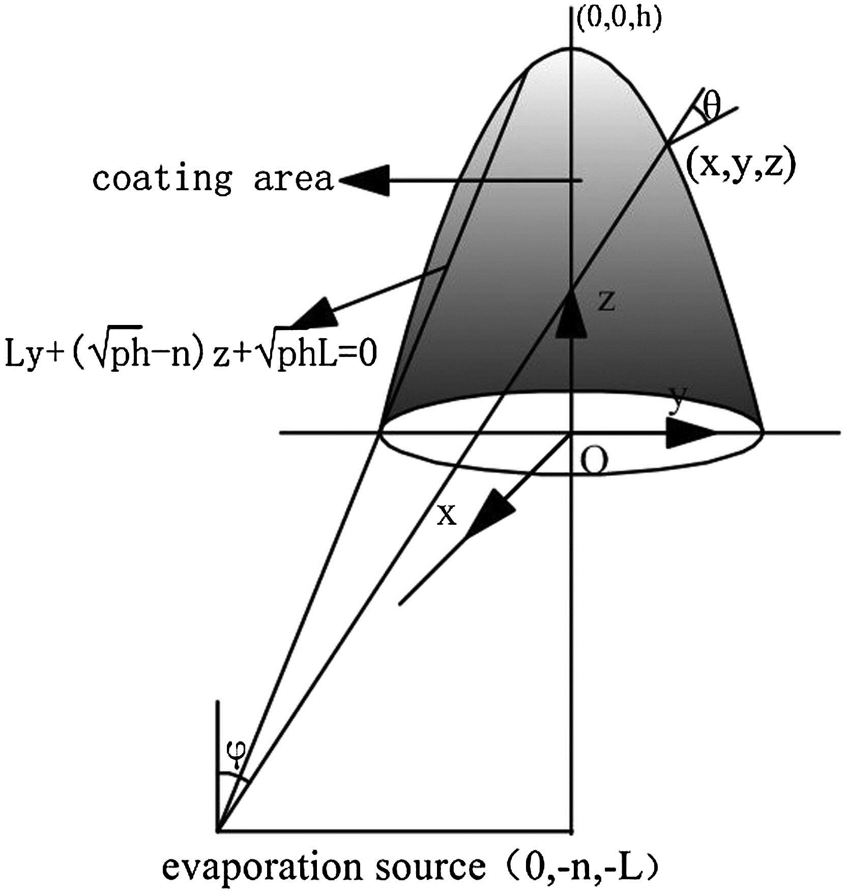
The configuration of the source-substrate system in the coating preparation on a parabolic substrate is shown in Fig. 1. The coordinate system is established with the center of the parabolic bottom as the origin. The coordinates of the parabolic vertex and the evaporation source are (0, 0, ) and (0, , ), where is the height of the substrate, and and are the horizontal distance and vertical height between the evaporation source and the center of the parabolic bottom, respectively. Suppose the parabolic focal length is , then the equation of the parabolic substrate is .
Sign up for Chinese Optics Letters TOC. Get the latest issue of Chinese Optics Letters delivered right to you!Sign up now
Figure 1.Configuration of source-substrate system in the film growth on parabolic substrate.
When the substrate is stationary, the arbitrary point of the coating area on the parabolic substrate meets the following conditions.
The distance between point A and the evaporation source can be expressed as
The angle between the normal of point A and the line composed by point A and the evaporation source can be expressed as
The emission angle between the normal of the surface source and the line composed by the source and point A meets the equation When the source is a point source, the film thickness of arbitrary point A around it is , where is the density of the film and is the total mass of the evaporation material[11]. With Eqs. (1) and (2), we can obtain
When the source is a surface source, the density of the vapor around it has a certain direction and the film thickness follows a cosine distribution. The film thickness of arbitrary point A around the surface source is [11]. With Eqs. (1)–(3),
Obviously, some areas cannot be coated when . The coating area can be calculated as follows: the interface of the coating area and the “blind” area is the intersection of a plane and a parabolic substrate, while the plane is parallel to the axis. Moreover, the evaporation source and point (0, , 0) belong to the plane. It can be obtained that the plane is
When the substrate is stationary, the coating area is the part facing the evaporation source divided by the plane , with , as shown in Fig. 1. When all of the parabolic substrates can be coated.
Under the situation that the substrate is rotating, some areas cannot be coated when , while all of the parabolic substrate can be coated when . In this Letter we only discuss the second condition.
As a result of the symmetry of the parabolic substrate, the film thickness is uniform at the same height. The film thickness at different heights deposited by a point source and a surface source can be expressed as where is the coated arc of the circle with as the height, as shown in Fig. 2. Obviously, for the substrate that is stationary with , there is a , when , where the whole circle can be coated. In other cases, is decided by Eq. (6), as shown in Fig. 2. is decided by . It can be obtained that
With Eqs. (4), (5), (7)–(9), suppose , , the film thickness of each point on the parabolic substrate can be expressed as when otherwise, ,
The coating thickness equation of each point on a parabolic substrate is shown in Eqs. (10)–(13) when the substrate is rotating.
The coating thickness distribution can be studied by calculating the relative thickness of the different heights and the vertex on the parabolic substrate. Based on Eq. (10), when it can be obtained that . Thus, the relative thickness of the different heights and the vertex on the parabolic substrate can be expressed as
Additionally, when , based on Eq. (11) it can be determined that . Thus, the relative thickness of the different heights and the vertex on a parabolic substrate can be express as
Figure 3 shows the impact of on the calculated coating thickness distribution on a parabolic substrate with and under different evaporation sources. It can be seen that the trend of the coating thickness distribution under different evaporation sources is uniform. The curve is smooth when is small. However, the curve breaks when due to the fact that, when the substrate is stationary, some areas cannot be coated as is small, while it is opposite as is large. Additionally, the maximum coating thickness appears at the bottom of the substrate when is small. The coating thickness is decreasing with the increase of the height. However, the minimum coating thickness does not appear at the vertex of the substrate, which is different with the hemisphere substrate[8]. The distribution of the coating thickness is changing with the increase of ; the maximum coating thickness appears at the vertex of the substrate. It can be seen that an excellent thickness uniformity of coating can be obtained when under the point source and when under the surface source.
Figure 3.With , the impact of on the calculated coating thickness distribution on parabolic substrate: (a) Point source and (b) surface source.
Figure 4 shows the impact of on the calculated coating thickness distribution on a parabolic substrate with and under different evaporation sources. It can be seen that the difference between the distributions of the coating thickness deposited by different sources is small when . The difference increases when decreases because is small when ; thus, the influence of on the coating thickness is small. Additionally, the maximum coating thickness appears at the vertex of the substrate when . The coating thickness is decreasing with the decrease of the height. What is more, the distribution of the coating thickness is changing with the decrease of ; the maximum coating thickness appears at the bottom of the substrate. It can be seen that an excellent thickness uniformity of coating can be obtained when under two different kinds of sources.
Figure 4.Impact of on the calculated coating thickness distribution on parabolic substrate with .
It can be seen that an excellent thickness uniformity of coating on a whole parabolic substrate can be obtained by choosing an appropriate configuration of an evaporation system under different evaporation sources. However, the requirement for the configuration of an evaporation system is quite rigorous and it is difficult to achieve. Under actual situations it is necessary to use some actions such as a modified plate and planetary rotation to improve the film thickness uniformity[12].
In conclusion, it is believed that by choosing the appropriate configuration of an evaporation system, a relatively homogeneous coating can be obtained on the whole inner face of the parabolic substrate. This study provides a theoretical basis for the improvement of thickness uniformity of coatings on parabolic substrates. Moreover, it has theoretical guiding significance for coating preparation on complex surface substrates. Meanwhile, a parabolic reflector with good uniformity definitely can be fabricated if it is supplemented by other means such as a correcting plate and planetary rotation.
Lingmao Xu, Jizhou Wang, Maojin Dong, Duoshu Wang, Yudong Feng. Theoretical study of the thickness uniformity of a coating on the inner face of a parabolic substrate in a vacuum evaporation system[J]. Chinese Optics Letters, 2015, 13(Suppl.): S22201