• Photonics Research
  • Vol. 10, Issue 11, 2607 (2022)
Jia-Zhi Yang1、†, Rui-Zhe Zhao2、†, Zhe Meng1, Jian Li1, Qing-Yuan Wu1, Ling-Ling Huang2、3、*, and An-Ning Zhang1、4、*
Author Affiliations
  • 1Center for Quantum Technology Research and Key Laboratory of Advanced Optoelectronic Quantum Architecture and Measurements (MOE), School of Physics, Beijing Institute of Technology, Beijing 100081, China
  • 2Beijing Engineering Research Center of Mixed Reality and Advanced Display, School of Optics and Photonics, Beijing Institute of Technology, Beijing 100081, China
  • 3e-mail:
  • 4e-mail:
  • show less
    DOI: 10.1364/PRJ.470537 Cite this Article Set citation alerts
    Jia-Zhi Yang, Rui-Zhe Zhao, Zhe Meng, Jian Li, Qing-Yuan Wu, Ling-Ling Huang, An-Ning Zhang. Quantum metasurface holography[J]. Photonics Research, 2022, 10(11): 2607 Copy Citation Text show less
    Schematic of quantum metasurface holography. The black arrow indicates the polarization state of incident photons, the red pattern indicates that the polarizer transmits horizontally polarized light, and the blue pattern indicates that the polarizer transmits vertically polarized light. On the right is the scanning electron microscope (SEM) image of our metasurface sample.
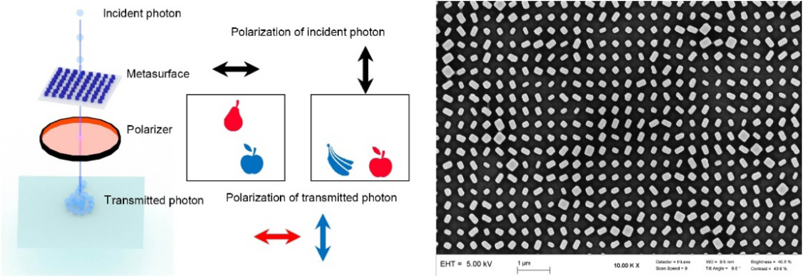
    Fig. 1. Schematic of quantum metasurface holography. The black arrow indicates the polarization state of incident photons, the red pattern indicates that the polarizer transmits horizontally polarized light, and the blue pattern indicates that the polarizer transmits vertically polarized light. On the right is the scanning electron microscope (SEM) image of our metasurface sample.
    Preparation of heralded single-photon source. PPKTP crystal is pumped by 405 nm CW laser with 20 mW output power. When passing through the crystal, some photons undergo the SPDC process and become entangled photon pairs. The photon pairs are separated by the PBS. One photon of the photon pairs (signal photon) is detected by SPAD (Excelitas Technologies SPCM-800-14-FC) as a trigger for the other photon. The other photon (idler photon) is coupled into SMF and transferred to the next section.
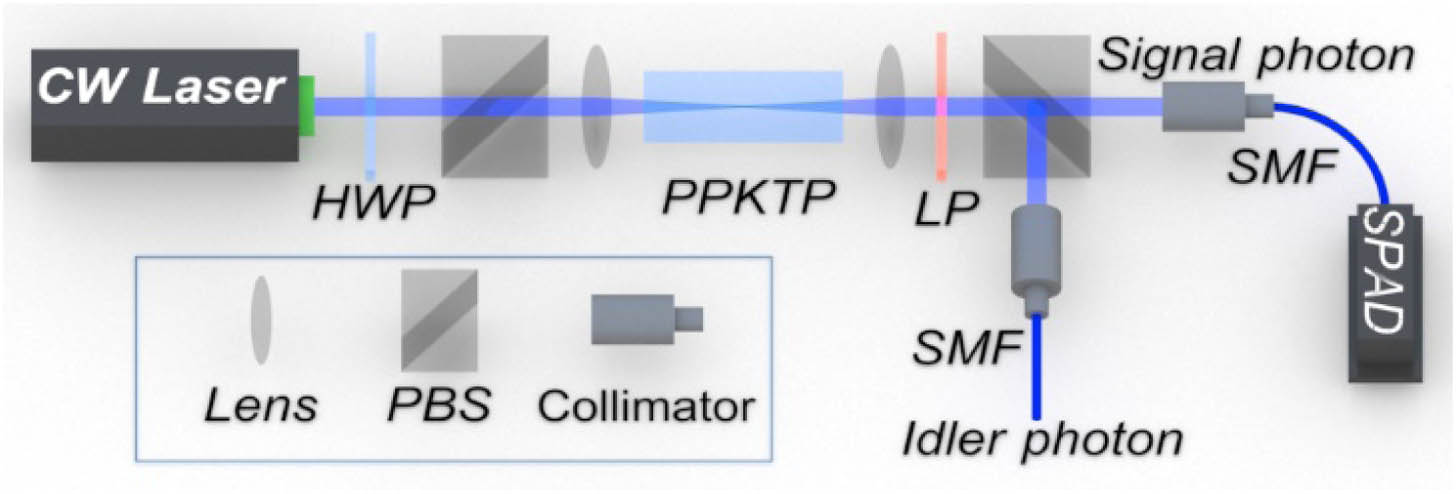
    Fig. 2. Preparation of heralded single-photon source. PPKTP crystal is pumped by 405 nm CW laser with 20 mW output power. When passing through the crystal, some photons undergo the SPDC process and become entangled photon pairs. The photon pairs are separated by the PBS. One photon of the photon pairs (signal photon) is detected by SPAD (Excelitas Technologies SPCM-800-14-FC) as a trigger for the other photon. The other photon (idler photon) is coupled into SMF and transferred to the next section.
    Experimental schematic of quantum metasurface holography. The idler photon after polarization modulation irradiates the metasurface sample. The beam radius on the metasurface sample is controlled by lens1. The metasurface sample modulates the spatial phase and polarization of idler photons. The beam radius of these idler photons is expanded by a 50× objective lens. Then, we use an HWP and a PBS to select the polarization state of these idler photons. The idler photons after polarization selection are focused by the len2. A raster scan system placed on the focal plane of len2 is used to obtain the reconstructed image.
    Fig. 3. Experimental schematic of quantum metasurface holography. The idler photon after polarization modulation irradiates the metasurface sample. The beam radius on the metasurface sample is controlled by lens1. The metasurface sample modulates the spatial phase and polarization of idler photons. The beam radius of these idler photons is expanded by a 50× objective lens. Then, we use an HWP and a PBS to select the polarization state of these idler photons. The idler photons after polarization selection are focused by the len2. A raster scan system placed on the focal plane of len2 is used to obtain the reconstructed image.
    Second-order correlation function of HSPS. The red and blue crosses show the experimental measurement gc(2)(τ) before and after the metasurface, respectively. The time interval between two adjacent points is 0.512 ns. The minimum measured gc(2)(τ) value of the HSPS before and after the metasurfaces is 0.0115±0.0002 and 0.0404±0.0028. The error bar represents the mean plus or minus the standard deviation.
    Fig. 4. Second-order correlation function of HSPS. The red and blue crosses show the experimental measurement gc(2)(τ) before and after the metasurface, respectively. The time interval between two adjacent points is 0.512 ns. The minimum measured gc(2)(τ) value of the HSPS before and after the metasurfaces is 0.0115±0.0002 and 0.0404±0.0028. The error bar represents the mean plus or minus the standard deviation.
    Contrast enhancement. (a) Raw data collected by the raster scan system. (b) Result after reducing the brightness of the central bright spot. (c) Result after reducing background noise. (d) Result after picture smooth treatment. (e) Regional division. (f) Flow chart of our algorithm.
    Fig. 5. Contrast enhancement. (a) Raw data collected by the raster scan system. (b) Result after reducing the brightness of the central bright spot. (c) Result after reducing background noise. (d) Result after picture smooth treatment. (e) Regional division. (f) Flow chart of our algorithm.
    Metasurface holography results. The first line is the result of simulation. The second line is the result of the CW laser and is imaged by CCD. The third line is the quantum holography result of HSPS and is imaged by the scanning system. Two arrows are displayed in the upper left of simulation result. The above arrow indicates the polarization state of the incident light while the arrow below indicates the polarization state of the transmitted light. The horizontal arrow represents the horizontally polarized light, the vertical arrow represents the vertically polarized light, the clockwise rotation arrow represents the right-handed circularly polarized light, and the counterclockwise rotation arrow represents the left-handed circularly polarized light.
    Fig. 6. Metasurface holography results. The first line is the result of simulation. The second line is the result of the CW laser and is imaged by CCD. The third line is the quantum holography result of HSPS and is imaged by the scanning system. Two arrows are displayed in the upper left of simulation result. The above arrow indicates the polarization state of the incident light while the arrow below indicates the polarization state of the transmitted light. The horizontal arrow represents the horizontally polarized light, the vertical arrow represents the vertically polarized light, the clockwise rotation arrow represents the right-handed circularly polarized light, and the counterclockwise rotation arrow represents the left-handed circularly polarized light.
    Jia-Zhi Yang, Rui-Zhe Zhao, Zhe Meng, Jian Li, Qing-Yuan Wu, Ling-Ling Huang, An-Ning Zhang. Quantum metasurface holography[J]. Photonics Research, 2022, 10(11): 2607
    Download Citation