1Center for Quantum Technology Research and Key Laboratory of Advanced Optoelectronic Quantum Architecture and Measurements (MOE), School of Physics, Beijing Institute of Technology, Beijing 100081, China
2Beijing Engineering Research Center of Mixed Reality and Advanced Display, School of Optics and Photonics, Beijing Institute of Technology, Beijing 100081, China
Metasurface holography has great application potential in the fields of optical display, optical storage, and security. Traditional metasurface holography uses the well-designed subwavelength structure to modulate the incident laser beam. Although many researches about laser metasurface holography have been realized, metasurface holography based on quantum light sources is rare. Here, we realized quantum metasurface holography through single-photon and multichannel polarization multiplexing metasurfaces, and we compared the quantum results with laser results. Our work proves that quantum light sources can be well modulated by the subwavelength structure of integrated metasurfaces and extend both fields of metasurfaces and quantum optics. This result shows that metasurfaces have the potential for use in various quantum devices to reduce the size of quantum devices, improve quantum efficiency, and enhance practicability, reliability, and accuracy.
1. INTRODUCTION
With the development of nanofabrication technologies, metasurfaces have gradually become a potential substitute of traditional optical elements due to their abilities to arbitrarily tailor the fundamental properties of light [1–8]. Various meaningful applications such as beam shaping [9,10], metalenses [11,12], holography [13,14], and nonlinear optics [15,16] have been demonstrated with the platform offered by metasurfaces. In recent years, the research of metasurfaces based on quantum optics has also attracted much attention. Some previous work about quantum mechanics by using metasurfaces has been reported [17–20]. For example, Wang et al. [21] realized multiphoton state reconstruction using metasurfaces. Li et al. [22] used metasurfaces to generate high-dimensional entanglement and multiphoton states. Zhou et al. [23] used metasurfaces to realize quantum edge detection, and Dalvit et al. tried to describe metasurfaces in the quantum regime [24] (see Fig. 1).
Among the above-mentioned applications, metasurface holography can exhibit superior performances over traditional holography based on spatial light modulator devices in certain areas [25,26]. Benefitting from the subwavelength period of metasurfaces, the reconstructed images of metasurface holography can achieve higher resolution with good quality, and the undesired diffraction orders can be successfully eliminated. Furthermore, the working bandwidth and field-of-view, as well as the space bandwidth product, can also be increased by utilizing elaborately designed metasurfaces [27].
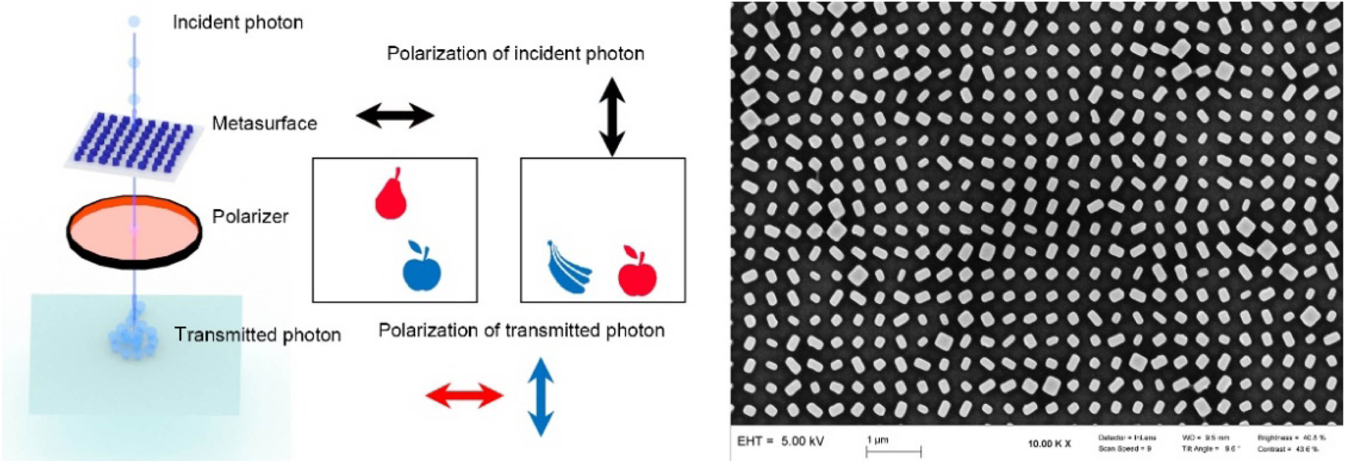
Figure 1.Schematic of quantum metasurface holography. The black arrow indicates the polarization state of incident photons, the red pattern indicates that the polarizer transmits horizontally polarized light, and the blue pattern indicates that the polarizer transmits vertically polarized light. On the right is the scanning electron microscope (SEM) image of our metasurface sample.
Whether the wave function is a physical reality or just a mathematical tool is a fundamental question in quantum theory. Since the 20th century, the discovery and discussion of the wave function physical reality, which was proposed by De Broglie and expanded by Bohm, have emerged one after another [28–34]. In this paper, our quantum metasurface holography experiment is new evidence for the wave function physical reality.
Sign up for Photonics Research TOC. Get the latest issue of Photonics Research delivered right to you!Sign up now
While previously reported metasurface holography works are usually explained by the classical electromagnetic wave theory, the quantum metasurface holography has not been implemented. In this paper, we realize quantum holographic metasurface imaging via the heralded single-photon source (HSPS). The single-photon wave packet can be used to realize the holography via metasurface, which proves that Von Neumann’s theory of wave packet collapse states can be used in subwavelength spatial scale. Our results show that such multichannel polarization multiplexing metasurfaces can be used for quantum dynamic vectorial holographic display. These results will provide a reference for the application of metasurfaces in quantum information research in the future.
2. METHODS
A. Design of Metasurfaces
A birefringent metasurface is demonstrated for realizing the reconstruction of different holographic images in different polarization channels. The designed metasurface is composed of an array of amorphous silicon (-Si) nanofins with different sizes and orientation angles on top of a glass substrate. By utilizing different input/output polarization states, three independent images (we choose the “apple,” “pear,” and “banana” patterns as the reconstructed images) and their combinations (“apple” “pear,” “pear” “banana,” “apple” “banana,” and “apple” “pear” “banana”) can be successfully reconstructed. This novel functionality can be contributed to the simultaneous and complete control of the phase and polarization of output light by analyzing the eigenvalue and eigenvector of the desired Jones matrix at each pixel. Meanwhile, a modified Gerchberg–Saxton scheme is adopted to generate multiple independent target phase profiles with quantified phase relations. Then, these phase profiles are successfully encoded into different polarization channels of a single metasurface (more details can be found in our previous works) [35].
The incident photons with specific polarization are modulated by the metasurface composed of subwavelength nanostructures. By selecting different incident and output polarization channels, different modulation patterns can be obtained in the -space of our metasurface. Here -space refers to the Fourier plane. The -space and image may be converted to one another using Fourier transform. In the continuous wave (CW) laser experiment, the incident light irradiates the entire metasurface sample, and the amplitude of each point on the image plane is equal to the coherent superposition from each point on the metasurface sample. However, in classical mechanics, a particle should only interact with part of the structure when passing through the metasurface sample, so the superposition in the image plane should be different from that in the laser, but our experimental results show that the image of the quantum light source is basically consistent with the laser image, which means that one single photon acts with the whole metasurface sample at the same time. Besides, our experiments also show that the single-photon wave packet is physical reality, and it can be modulated by the subwavelength microstructure. Therefore, the metasurface can be used in various quantum devices to reduce the size of quantum devices, improve quantum efficiency, and enhance practicability, reliability, and accuracy.
B. Preparation of Heralded Single-Photon Source
Here we use spontaneous parametric down-conversion (SPDC) technology to prepare the HSPS, and the setup is shown in Fig. 2. The light source is a 405 nm CW laser with 20 mW output power. The polarization and intensity of the laser are controlled by a half-wave plate (HWP) and a polarizing beam splitter (PBS). The polarization of light passing through the PBS is horizontal. The horizontally polarized laser is then focused to the center of the periodically poled potassium titanyl phosphate (PPKTP) crystal by a lens. Some of the photons passing through the PPKTP undergo the SPDC process to generate entangled photon pairs. The wavelength of these entangled photon pairs is twice that of incident photon, that is, 810 nm, and the polarization is orthogonal. These entangled photons are then collimated by a lens. A long pass filter (LP) is placed after the lens to block the 405 nm laser. A PBS separates the entangled photon pairs. One photon of the photon pairs, which is called the signal photon, is coupled into single-mode fiber (SMF) by a collimator and connected directly to a single-photon avalanche photodiode (SPAD) as a trigger for the other photon. The other photon, which is called the idler photon, is also coupled into SMF by a collimator and sent out to the subsequent experimental device (shown in Fig. 3) as a single-photon source.
Figure 2.Preparation of heralded single-photon source. PPKTP crystal is pumped by 405 nm CW laser with 20 mW output power. When passing through the crystal, some photons undergo the SPDC process and become entangled photon pairs. The photon pairs are separated by the PBS. One photon of the photon pairs (signal photon) is detected by SPAD (Excelitas Technologies SPCM-800-14-FC) as a trigger for the other photon. The other photon (idler photon) is coupled into SMF and transferred to the next section.
Figure 3.Experimental schematic of quantum metasurface holography. The idler photon after polarization modulation irradiates the metasurface sample. The beam radius on the metasurface sample is controlled by lens1. The metasurface sample modulates the spatial phase and polarization of idler photons. The beam radius of these idler photons is expanded by a objective lens. Then, we use an HWP and a PBS to select the polarization state of these idler photons. The idler photons after polarization selection are focused by the len2. A raster scan system placed on the focal plane of len2 is used to obtain the reconstructed image.
The metasurface holography experimental device is shown in Fig. 3. The idler photon of the HSPS is emitted from a collimator and is then modulated by the system composed of quarter-wave plate (QWP), HWP, and PBS1. Unlike lasers, our HSPS is particularly weak; therefore, it is necessary to reduce the loss as much as possible. Only one HWP cannot modulate all idler photons into horizontal polarization because our fiber is not polarization maintaining fiber. Some photons will go to the vertical output of PBS1. By using the system composed of the QWP, HWP, and PBS1, we can modulate almost all photons emitted from the collimator to have horizontal polarization, so as to increase the light intensity. In addition, we place a collimator at the vertical output of PBS1 to collect photons. These photons are transmitted to the SPAD through multi-mode fiber (MMF). SPAD converts the optical signal into electrical signal and sends it to time-correlated single-photon counting (TCSPC). TCSPC can record the arrival time of the signal very accurately (64 ps) and then send the data to the computer for subsequent processing. By monitoring the counting rate of this detector, we know the number of photons entering the holographic imaging system. Before the experiment, we will minimize the counting rate of this detector by rotating QWP and HWP.
The horizontal polarization light passing through PBS1 then changed the polarization state through HWP or QWP. Here, HWP and QWP do not exist in the optical path at the same time. There is only HWP when measuring linear polarization and QWP when measuring circular polarization. After the polarization state of the incident light is adjusted, it is focused by lens1 and irradiates on the metasurface. The light passing through the metasurface is expanded by a objective lens, and the output polarization state is controlled by a polarization selection system composed of HWP or QWP and PBS2. Then, it is focused by lens2 and detected on the focal plane of lens2. In the quantum imaging experiment, we use a raster scan system to record data. In the classical laser experiment, we replace the idler photons with the continuous laser, and we replace the raster scan system with charge-coupled device (CCD).
The raster scan system consists of two motorized linear stages and an MMF with a fiber connector. The orthogonal combination of the two motorized linear stages allows the fiber connector to move on the focal plane of lens2. The core diameter of our MMF is 62.5 μm. The MMF transmits data to an SPAD and sends it to TCSPC. Through the coincidence measurement of the signal photon and idler photon passing through the metasurface, we realize HSPS-based quantum metasurface holography.
3. RESULTS
A. Testing Second-Order Correlation Function
The second-order correlation functions can be used to describe the relationship between intensity fluctuations at different times and , where . The Hanbury–Brown–Twiss experiment [36,37] shows that of laser, thermal light, and quantum light sources are different. The of quantum light source is usually less than 1. We measured the of our HSPS, and the results of the are shown in the red curve in Fig. 4. , and this result shows that our light source is a quantum light source. Meanwhile, we measured the second-order correlation function of the light passing through the metasurfaces to find whether the metasurfaces will change the distribution of the light source. Both before and after the metasurface, are measured by using a coupler to collect all photons—in other words, all points of the image plane are considered. The blue curve of Fig. 4 shows the of the light after passing through the metasurfaces. It can be seen that there is an obvious valley. The minimum value of this valley is . Therefore, the single photon passing through the metasurface is still a good quantum light.
Figure 4.Second-order correlation function of HSPS. The red and blue crosses show the experimental measurement before and after the metasurface, respectively. The time interval between two adjacent points is 0.512 ns. The minimum measured value of the HSPS before and after the metasurfaces is and . The error bar represents the mean plus or minus the standard deviation.
Some of the raw data of quantum metasurface holography collected by the raster scan system are shown in the Fig. 5(a). Due to the existence of the central bright spot and statistical fluctuation, the contrast of the picture is low, and we can hardly see the target image. In fact, the central bright spots are not desired in our design. Those central bright spots come from the structural defects and unavoidable discrete nature of metasurface. From the simulation in Fig. 6, we can see that there are no bright spots in the center. Therefore, we need to improve the contrast of these raw data. Assuming that the original picture is represented by , is the set of all positive integers, and and represent the number of row and column elements of matrix , respectively. Matrix can be expressed as the superposition of background noise and target signal . The background noise of each pixel obeys the same statistical distribution. The signal region can be divided into three regions: central bright spot region , signal region , and another region . Subscripts 0, 1, 2 indicate different regions for matrices , , and : central bright spot region 0, signal region 1, and another region 2, respectively. As shown in Fig. 5(e), region is the target region of our imaging, and bright spot region and other region are noise regions. The intensity of bright spot region is much higher than that of signal region , and the intensity of another region is almost zero. In order to improve the image contrast, we need to reduce the brightness of and suppress the background noise .
Figure 5.Contrast enhancement. (a) Raw data collected by the raster scan system. (b) Result after reducing the brightness of the central bright spot. (c) Result after reducing background noise. (d) Result after picture smooth treatment. (e) Regional division. (f) Flow chart of our algorithm.
Figure 6.Metasurface holography results. The first line is the result of simulation. The second line is the result of the CW laser and is imaged by CCD. The third line is the quantum holography result of HSPS and is imaged by the scanning system. Two arrows are displayed in the upper left of simulation result. The above arrow indicates the polarization state of the incident light while the arrow below indicates the polarization state of the transmitted light. The horizontal arrow represents the horizontally polarized light, the vertical arrow represents the vertically polarized light, the clockwise rotation arrow represents the right-handed circularly polarized light, and the counterclockwise rotation arrow represents the left-handed circularly polarized light.
First, we consider reducing the brightness of . To make the signal area look clearer, we can normalize the image by taking the brightest point in the signal area as the maximum intensity point of the whole picture. Since the number of photons in the signal area is small, the shot noise of each pixel is relatively large. Pixels with significantly higher intensity than that of other pixels may also appear in the signal area. To reduce the impact of shot noise, we need to find a suitable maximum value. Therefore, we propose and develop a method to sort the data in by comparison between adjacent data until we find an appropriate maximum value . Any point in whose brightness exceeds will reduce the brightness to . Then, we scale the intensity value of the whole graph to the [0,1] interval. Through this operation, we can suppress some noise coming from and improve the contrast. The result after this process is shown in Fig. 5(b).
Then, we need to suppress the background noise. First, we need to determine the composition of the background noise. The background noise is mainly composed of Gaussian noise and Poisson noise. We make statistics on the noise area and find that the average value is equal to variance. Therefore, we believe that the background noise in this experiment mainly comes from Poisson noise . represents the average value of Poisson distribution. Using the recursive formula of Poisson distribution, we can get the Poisson probability of any number. Here we choose 90% as the noise threshold—that is, 90% of the probability of noise is less than the threshold. Then, we suppress background noise by subtracting this number from original picture . The results after this process are shown in Fig. 5(c).
The above steps are processed pixel by pixel. Next, we consider the correlation between pixels to smooth the image. Proper smoothing can improve the image quality. The block-matching and 3D filtering (BM3D) algorithm [38,39] is a smoothing and denoising algorithm. The BM3D algorithm will find similar blocks around the smoothed area before smoothing, and considering the relationship between these similar blocks, the processing can achieve a better denoising effect. The image processed by the BM3D algorithm is shown in Fig. 5(d).
After the above processing, the image contrast of quantum metasurface holography can be effectively enhanced. That is to say, by using the quantum metasurface holography enhancement (QMHE) algorithm, we realized quantum metasurface holography imaging. The results are shown in Fig. 6.
Our raster scan system uses 62.5 μm MMF, and the scanning steps in and directions are all 50 μm. The photon counting rate of the signal region is about 100, and the acquisition time of each pixel is 1 s. Figure 6 shows that the results of laser holographic reconstruction are basically consistent with those of HSPS holographic reconstruction. The scanning result is pixels. Although the resolutions of the raster scan system and CCD are a bit different, we can see that the shape and intensity of the reconstructed holographic images from both the CW laser and quantum source are almost the same. In the results of circularly polarized light, the banana pattern is not obvious due to insufficient intensity, but it still exists. In the RL and LR column, we can even observe the intensity difference of the three objects. Pear has the highest intensity, apple is slightly lower, and banana is the weakest, which results from the energy efficiencies of metasurfaces in these three channels. Based on the above results, we believe that the metasurface sample can modulate the quantum light, and the modulation of the laser and single photon by the metasurface is basically the same. That is to say, quantum wave function is a physical reality that can correctly describe the state of particle propagation and can be modulated by subwavelength structures. The experiment based on lasers can be explained by the classical wave optics theory that the amplitude of each point on the image plane is equal to the coherent superposition from each point on the metasurface sample. But the experiment based on quantum light needs quantum theory to describe. Due to the particle property of the single photon, the photon should only interact with part of the structure when passing through the metasurface sample. This result shows that the wave function is a physical reality, and the propagation of photons needs to be described by the wave function. It collapses to a specific state only when it is detected. All above experimental results show that metasurfaces have potential for use in various quantum devices to reduce the size of quantum devices, improve quantum efficiency, and improve practicability, reliability, and accuracy.
4. DISCUSSION
In this paper, we realize multichannel metasurface holographic imaging based on HSPS. Although the intensity of HSPS is weak, we completed the experiment by improving the system efficiency and using the QMHE algorithm. We improved the photon counting rate and used a priori knowledge to suppress the noise signal and improve the contrast of the imaging results. This result shows that quantum wave function is a physical reality and quantum wave function can be modulated by subwavelength structures. The interaction between the quantum system and the classical environment refers to the interaction between the single photon and the metasurface, which constitutes a projection measurement. The metasurface completes a polarization measurement under H-polarized measurement basis and V-polarized measurement basis of the input photon. The double-slit experiment demonstrated a quantum phenomenon that could not be explained by any classical theory, and it contained the core idea of quantum mechanics. Our experiment can be understood as the subwavelength counterpart of single-photon double-slit interference, indicating that the photons shows wave-particle duality and can be described by the wave function. Compared with other metasurface experiments based on quantum light sources, our quantum metasurface holographic technology realized the complete continuous regulation of a two-dimensional quantum light field. Besides, the potential of metasurface devices for quantum information devices is also displayed. We hope our results will benefit metasurface and quantum information research.