• Photonics Research
  • Vol. 5, Issue 3, 245 (2017)
Jing Cao1, Pinghe Wang1, Yan Zhang2, Guohua Shi1、3、*, Bo Wu4, Shangjian Zhang1, and Yong Liu1
Author Affiliations
  • 1State Key Laboratory of Electronic Thin Films and Integrated Devices, School of Optoelectronic Information, University of Electronic Science and Technology of China, Chengdu 610054, China
  • 2School of Electronic and Communication Engineering, Guiyang University, Guiyang 550005, China
  • 3Suzhou Institute of Biomedical Engineering and Technology, Chinese Academy of Sciences, Suzhou 215163, China
  • 4College of Optoelectronic Technology, Chengdu University of Information Technology, Chengdu 610225, China
  • show less
    DOI: 10.1364/PRJ.5.000245 Cite this Article Set citation alerts
    Jing Cao, Pinghe Wang, Yan Zhang, Guohua Shi, Bo Wu, Shangjian Zhang, Yong Liu. Methods to improve the performance of the swept source at 1.0  μm based on a polygon scanner[J]. Photonics Research, 2017, 5(3): 245 Copy Citation Text show less
    Schematic of the structure of the swept source.
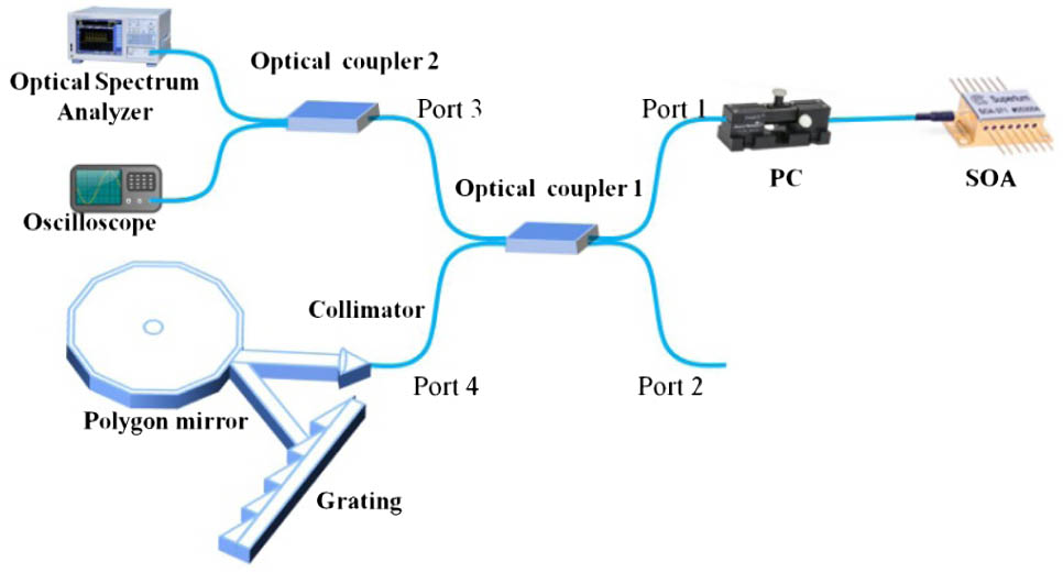
    Fig. 1. Schematic of the structure of the swept source.
    Schematic of booster structures: (a) buffered structure, (b) secondary amplifier structure, and (c) dual-SOA structure.
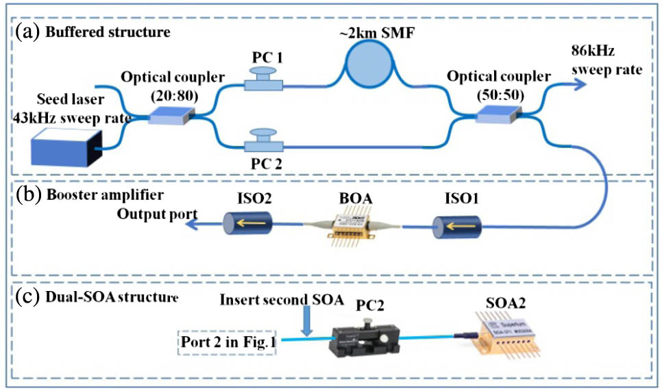
    Fig. 2. Schematic of booster structures: (a) buffered structure, (b) secondary amplifier structure, and (c) dual-SOA structure.
    Single wavelength output of the swept source when the polygon scanner stops.
    Fig. 3. Single wavelength output of the swept source when the polygon scanner stops.
    Output of the swept source with different cavity lengths. (a) Output spectra of the swept source. (b) Oscilloscope trace of the swept source.
    Fig. 4. Output of the swept source with different cavity lengths. (a) Output spectra of the swept source. (b) Oscilloscope trace of the swept source.
    Output of the swept source with different rotating speeds of polygon mirror. (a) Output spectra of the swept source. (b) Oscilloscope trace of the swept source.
    Fig. 5. Output of the swept source with different rotating speeds of polygon mirror. (a) Output spectra of the swept source. (b) Oscilloscope trace of the swept source.
    Output of the swept source with different coupling ratios. (a) Output spectra of the swept source. (b) Oscilloscope trace of the swept source.
    Fig. 6. Output of the swept source with different coupling ratios. (a) Output spectra of the swept source. (b) Oscilloscope trace of the swept source.
    Output of the swept source with buffered and without buffered. (a) Output spectra of the swept source. (b) Oscilloscope trace of the swept source.
    Fig. 7. Output of the swept source with buffered and without buffered. (a) Output spectra of the swept source. (b) Oscilloscope trace of the swept source.
    Injected currents changed from 50 to 300 mA. (a) Output spectra of the laser. (b) Output power versus the injected current.
    Fig. 8. Injected currents changed from 50 to 300 mA. (a) Output spectra of the laser. (b) Output power versus the injected current.
    Output of the swept source with SOA1+SOA2. (a) Output spectra of the swept source. (b) Oscilloscope trace of the swept source.
    Fig. 9. Output of the swept source with SOA1+SOA2. (a) Output spectra of the swept source. (b) Oscilloscope trace of the swept source.
    Jing Cao, Pinghe Wang, Yan Zhang, Guohua Shi, Bo Wu, Shangjian Zhang, Yong Liu. Methods to improve the performance of the swept source at 1.0  μm based on a polygon scanner[J]. Photonics Research, 2017, 5(3): 245
    Download Citation