Abstract
In this work, we investigate the methods to improve the performance of the swept source at 1.0 μm based on a polygon scanner, including in-cavity parameters and booster structures out of the cavity. The three in-cavity parameters are the cavity length, the rotating speed of the polygon scanner, and the in-cavity energy. With the decrease of cavity length, the spectrum bandwidth becomes wider and the duty cycle becomes higher. With the increase of the rotating speed of the polygon, the spectrum bandwidth becomes narrower, and the duty cycle becomes lower but the repetition rate becomes higher. With more energy in-cavity, the spectrum bandwidth becomes wider and the duty cycle becomes higher. The booster structures include the buffered structure, secondary amplifier, and dual-semiconductor optical amplifier configuration, which are used to increase the sweep frequency to 86 kHz, the output power to 18 mW, and the tuning bandwidth to 131 nm, respectively.1. INTRODUCTION
Swept sources have long been widely used in biomedical imaging, especially for swept-source optical coherence tomography (SSOCT) [1–3]. Typical short cavity swept sources consist of a broadband gain medium, a wavelength-selection filter, and an optical coupler (OC) used as feedback and output. While the performance of these kinds of swept sources is limited by the cavity length [4], one way to overcome this problem is to shorten the cavity length; micro-electromechanical systems (MEMS) technology has been used on swept sources, including MEMS Fabry–Perot tunable filters, MEMS mirrors with grating filters, and MEMS vertical-cavity surface-emitting lasers (VCSELs) [5–7]. Another way is a swept source based on Fourier domain mode locking (FDML) technology, by introducing a several-kilometer single-mode fiber (SMF) in the cavity, meanwhile periodically driving the optical bandpass filter synchronously with the optical round-trip time of the light [8]. There are mainly four central wavelength swept sources, including 850 [9], 1050 [10–12], 1310 [4,8], and 1550 nm [13], used in the SSOCT system. It is demonstrated that SSOCT at the 1050 nm wavelength range is best for imaging in human retina and choroid layers, since the absorption of water at the 1050 nm range is lower than at the 1310 nm range, the scattering at the 1050 nm water window is reduced compared to that at 850 nm [10], and the dispersion of water near 1050 nm is zero [14]. All these advantages mean that swept sources at 1050 nm wavelengths play an important role in ophthalmic OCT [15,16].
Typical wavelength-selection mechanisms used in swept sources include the polygon scanner filter and the optical Fabry–Perot filter [17]. Polygon scanner filters are flexible in structures, such as in telescope configurations [18] and in Littrow [19] and Littman [20] configurations. They have other advantages including high free spectral range (FSR), realizable uni-directionality, and high sweep rate. In the Littrow configuration, employing prisms before the polygon scanner [21] and using multiple reflection facets of the polygon scanner and grating illuminations in one sweep [22] are methods used to decrease the instantaneous linewidth of the swept source; prisms after the polygon scanner are used to demonstrate the linear sweep over time [23].
Many efforts have been made to improve the performance of the swept source. The parameters of a swept source directly determine the performance of SSOCT, such as the broad sweep range for high axial resolution, the high repetition rate for fast imaging speed, and the high output power for strong sensitivity. The k-linearity wavenumber laser based on an acousto-optic deflector filter can enhance the imaging speed by avoiding data resampling and recalibration [24]. A swept source with an ultrawide tuning range at 1.3 μm has been demonstrated by combining multiple semiconductor optical amplifiers (SOAs) with different gain regions [25,26]. A wide tuning range swept source with single SOA at 1.0 μm is achieved by adjusting the temperature of the thermoelectric (TE) cooler of the SOA [27]. An all-optical and stable inertia-free swept source has been demonstrated with an ultrafast sweep rate of 28 MHz at 1.0 μm [28]. By using an optical delay line to buffer the sweeps, the swept source can achieve an ultrahigh repetition rate [11,29]. There are two methods to achieve high output power of a swept source; one is using a boost amplifier after the seed laser [30], and the other is the combination of a tapered amplifier and SOA [31], or a ytterbium-doped fiber amplifier and SOA as the gain medium in the cavity [10].
Sign up for Photonics Research TOC. Get the latest issue of Photonics Research delivered right to you!Sign up now
In this paper, we investigate the methods in-cavity and out-of-cavity to improve the performance of the swept source at 1 μm, based on a polygon scanning filter in a Littrow arrangement. First, the performance of the swept source has been improved by optimizing three in-cavity parameters: the cavity length, the rotating speed of the polygon scanner, and the energy in the cavity. Then, in order to further improve the performance of the laser, booster structures out of the cavity, including the buffered structure, booster amplifier, and dual-SOA structure, were used to double the sweep rates to 86 kHz, increase output power to 18 mW, and improve bandwidth to 131 nm, respectively.
2. EXPERIMENTAL SETUP
Figure 1 depicts the laser configuration. It comprises a broad-bandwidth SOA (SOA-521, Superlum. Inc.), a fiber-optic coupler, a polarization controller (PC), and a tunable filter. A pilot controller (Pilot4-AC, Superlum. Inc.) is used to drive the SOA, when the applied forward current and temperature are 201.9 mA and , respectively, and the central wavelength of the SOA is 1020 nm. The tunable filter comprises a fiber-optic collimator, a polygon scanner (Lincoln laser, Inc.) with 90 facets, and a diffraction grating (1200 lines/mm). In this paper, when the polygon scanner is set at 960 r/s, the real rotating speed is 480 r/s (half of the setting value). The FSR [22] of this filter is determined by the following equation: where is the grating pitch, is the sweep angle range, and is the incident angle corresponding to the central wavelength. In our case, the beam width from the collimator is 2.8 mm; it is bigger than the facet width of the polygon, so the sweep angle range is (double of the polygon’s facet angle). According to Eq. (1), the FSR of this filter is 181.7 nm.
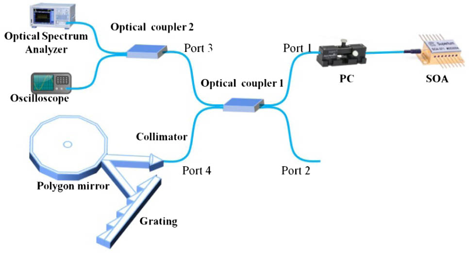
Figure 1.Schematic of the structure of the swept source.
The performance of the swept source can be further improved by booster structures, the repetition rate can be doubled by the buffered structure, the output power can be enhanced by the secondary amplifier, and the scanning bandwidth can be broadened by adding a gain module. In our case, the seed swept source has a 50:50 OC with a fiber length of 20 cm, the rotating speed of the polygon scanner is 960 r/s, and the duty cycle is 48%.
Figure 2 shows the booster structures of the swept source. Figure 2(a) is the buffered structure. The light from the swept source is split by a 20:80 fiber coupler, so 20% of the light is directly connected to one port of the 50:50 fiber coupler, and the other 80% of the light is connected by a 2 km SMF, which is used to delay the light by one half of the sweep period; the combination of the original and delay pulse trains can double the sweep rates. Since the buffered structure can decrease the output power of the laser, a booster optical amplifier (BOA) (BOA1137S, Thorlabs. Inc.) was used to improve the output power of the laser. Two isolators are employed before and after the BOA to make sure that light is uni-directional, as shown in Fig. 2(b).

Figure 2.Schematic of booster structures: (a) buffered structure, (b) secondary amplifier structure, and (c) dual-SOA structure.
In order to get a wider tuning rage, another SOA (SOA-481, Superlum. Inc.) is inserted into the cavity at port 2, as shown in Fig. 2(c). A current and temperature module (Conquer, Inc.) is used to drive the second SOA, when the applied forward current and temperature are 200 mA and , respectively, and the central wavelength of the second SOA is located at 950 nm. It can extend the scanning range at short wavelength. The combination of these SOAs with different gain regions can overcome the limited spontaneous emission spectrum from single SOA [25,26].
3. OPTIMAL IN-CAVITY PARAMETERS OF THE POLYGON-BASED SWEPT SOURCE
The in-cavity parameters directly determine the performance of a swept source; for the swept source in Fig. 1, the changeable optical components include the fiber coupler and the speed of the polygon, so we have OCs with different fiber lengths for different cavity lengths, polygon scanners at different rotating speeds for different repetition rates, and OCs with different coupling ratios for different in-cavity energy. In this section, we discuss the relationships between the performance of the laser and these three in-cavity parameters.
The linewidth of the swept source is measured when it is configured with a 50:50 OC with a fiber length of 20 cm. Figure 3 shows the single wavelength output of the source when the polygon scanner stops; when the wavelengths change from 1000 to 1080 nm at a 10 nm interval, the corresponding linewidths (at 3 dB) are 0.1, 0.1, 0.06, 0.06, 0.1, 0.06, 0.08, 0.08, and 0.16 nm, respectively.
Figure 3.Single wavelength output of the swept source when the polygon scanner stops.
The performance of the swept source is related to the cavity length. Figure 4(a) shows the output spectra at different fiber lengths. Figure 4(b) shows the oscilloscope trace. The pigtail of the SOA is 20 cm, and the optical path of the filter is 10 cm; when the fiber lengths of the OCs are 20, 30, and 50 cm, the total cavity lengths are 70, 90, and 130 cm, respectively. When the fiber lengths of OCs are 50, 30, and 20 cm, the spectrum bandwidths are 78 nm (1000–1078 nm), 86 nm (994–1080 nm), and 90 nm (994–1084 nm), and the duty cycles are 39.6%, 43.6%, and 48%. As the rotating speed is 960 r/s, the repetition rate is 43 kHz. By decreasing the cavity length, it will take less time for single wavelength light to build up a laser in the cavity. Meanwhile the rotational period of the polygon is unchanged, so the output spectrum bandwidth becomes wider. Since the FSR is unchanged, the duty cycle is proportional to the spectrum bandwidth (duty cycle = spectrum bandwidth/FSR), so it is also increased. This can explain the experimental results that the spectrum bandwidth and duty cycle could be increased by decreasing the cavity length.
Figure 4.Output of the swept source with different cavity lengths. (a) Output spectra of the swept source. (b) Oscilloscope trace of the swept source.
The rotating speed of the polygon scanner affects the performance of the swept source. There are three kinds of speeds for selection—240, 480, and 960 r/s, respectively. Figure 5(a) shows the output spectra at different rotating speeds. Figure 5(b) shows the oscilloscope trace. When the rotating speeds are 240, 480, and 960 r/s, the spectrum bandwidths are 97 nm (985–1082 nm), 96 nm (986–1082 nm), and 90 nm (994–1084 nm), the duty cycles are 54%, 53%, and 48%, and the repetition rates are 11.0, 21.7, and 43.3 kHz. Since the repetition rate equals the rotating speed of the polygon multiplied by the number of the mirror facets (repetition rate = rotating speed * facet number), the facet number is unchanged, so the repetition rate becomes higher with the increase of the rotating speed. While a faster rotating speed means a smaller rotational period, the time left to build up the laser is decreased, so the spectrum bandwidth becomes narrower. This can explain the experimental results that with the increase of the rotating speed, the repetition rate becomes higher, the spectrum bandwidth becomes narrower, and the duty cycle becomes lower.
Figure 5.Output of the swept source with different rotating speeds of polygon mirror. (a) Output spectra of the swept source. (b) Oscilloscope trace of the swept source.
The energy in the cavity influences the performance of the swept source. When the coupling ratios of OCs are 30:70 and 50:50, the percentage of light in the cavity is 70% and 50%, respectively. Figure 6(a) shows the output spectra with different coupling ratios. Figure 6(b) shows the oscilloscope trace. When the percentage of energy in-cavity decreases from 70% to 50%, the spectrum bandwidth changes from 103 nm (985–1088 nm) to 90 nm (994–1084 nm), and the duty cycle changes from 55% to 48%. As the rotating speed is 960 r/s, the repetition rate is constant at 43 kHz. The swept source is sensitive to its thresholding energy, so the bandwidth would be wider with more energy in the cavity. This can explain the experimental results that with a lower percentage of light in the cavity, the bandwidth is narrower, the duty cycle is decreased, and the repetition rate is unchanged.
Figure 6.Output of the swept source with different coupling ratios. (a) Output spectra of the swept source. (b) Oscilloscope trace of the swept source.
According to the experimental results above, the spectrum bandwidth and duty cycle could be increased by decreasing the cavity length. The repetition rate would become higher with the increase of rotating speed. The spectrum bandwidth and duty cycle could be increased by keeping a higher percentage of light in the cavity.
4. PERFORMANCE IMPROVEMENT BY BOOSTER STRUCTURE
The repetition rate is limited by the facet number and maximum rotating speed of the polygon; the buffered structure out of the cavity can further increase the repetition rate of the swept source. Figure 7(a) shows the output spectra of the laser with buffered and without buffered. Figure 7(b) shows the oscilloscope trace. Compared with the laser without buffered structure, the repetition rate increases to 86 kHz and the duty cycle increases to around 100% of the laser with the buffered structure. The doubled repetition rate is helpful in increasing imaging speed in SSOCT.
Figure 7.Output of the swept source with buffered and without buffered. (a) Output spectra of the swept source. (b) Oscilloscope trace of the swept source.
The booster amplifier can effectively improve the output power of the swept source. Figure 8(a) shows the output spectra of the laser with BOA at different injected currents. When the currents of BOA change from 50 to 300 mA with a 50 mA interval, the output power becomes higher. But this would bring some distortion on its spectrum shape, compared with the condition without BOA. This is because the gain spectra between BOA and SOA are different. When the injected current changes from 50 to 300 mW, the output power changes from 1.4 to 18 mW; it is increased linearly with injected current, as shown in Fig. 8(b).
Figure 8.Injected currents changed from 50 to 300 mA. (a) Output spectra of the laser. (b) Output power versus the injected current.
The use of multiple gain media provides a great improvement in the tuning range of the swept source; it would benefit the axial resolution in SSOCT. Figure 9(a) shows the output spectra with an inserted second SOA. Figure 9(b) shows the oscilloscope trace. Compared with a single SOA configured swept source, the spectrum bandwidth changes from 87 to 131 nm (945–1076 nm), the duty cycle changes from 48% to 62%, the central wavelength changes from 1041 to 1000.8 nm, and the output power changes from 2.1 to 6.12 mW of the swept source with two SOAs, respectively. Since the output spectrum is not an ideal Gaussian shape, a feasible method to solve this problem is adjusting the energy ratios of different wavelengths of light in the cavity, for example, using an OC with a different coupler ratio.
Figure 9.Output of the swept source with . (a) Output spectra of the swept source. (b) Oscilloscope trace of the swept source.
The booster structures out of the cavity including the buffered structure, secondary amplifier, and dual-SOA configuration could be used to further improve the performance of the swept source on its sweep frequency up to 86 kHz, output power up to 18 mW, and tuning bandwidth up to 131 nm, respectively.
5. CONCLUSION
In conclusion, we investigate the methods to improve the performance of the swept source at 1.0 μm based on a polygon scanner, including in-cavity parameters and out-of-cavity booster structures. Three in-cavity parameters—cavity length, rotating speed of polygon mirror, and energy in-cavity, could be adjustable to optimize the key parameters of the swept source, the spectrum bandwidth and duty cycle could be increased by either decreasing the cavity length or keeping more energy in the cavity, and the repetition rate would become higher with the increase of the rotating speed. It is useful to choose optical components for better performance of the swept source. The booster structures out of the cavity, including the buffered structure, secondary amplifier, and dual-SOA configuration, could been used to further improve the performance of the seed swept source on its sweep frequency up to 86 kHz, output power up to 18 mW, and tuning bandwidth up to 131 nm, respectively. This work has an important application in improving the performance of the polygon-based swept source, which could enhance the imaging quality of the SSOCT system.
References
[1] S. R. Chinn, E. Swanson, J. G. Fujimoto. Optical coherence tomography using a frequency-tunable optical source. Opt. Lett., 22, 340-342(1997).
[2] S. H. Yun, C. Boudoux, M. C. Pierce, J. F. de Boer, G. J. Tearney, B. E. Bouma. Extended-cavity semiconductor wavelength-swept laser for biomedical imaging. IEEE Photon. Technol. Lett., 16, 293-295(2004).
[3] S. H. Yun, G. J. Tearney, J. F. de Boer, N. Iftimia, B. E. Bouma. High-speed optical frequency-domain imaging. Opt. Express, 11, 2953-2963(2003).
[4] R. Huber, M. Wojtkowski, K. Taira, J. G. Fujimoto, K. Hsu. Amplified, frequency swept lasers for frequency domain reflectometry and OCT imaging: design and scaling principles. Opt. Express, 13, 3513-3528(2005).
[5] K. Totsuka, K. Isamoto, T. Sakai, A. Morosawa, C. H. Chong. MEMS scanner based swept source laser for optical coherence tomography. Proc. SPIE, 7554, 75542Q(2010).
[6] V. Jayaramana, D. D. Johna, C. Burgnera, M. E. Robertsona, B. Potsaidb, J. Y. Jiangb, T. H. Tsaic, W. Choic, C. D. Luc, P. J. S. Heimb, J. G. Fujimotoc, A. E. Cableb. Recent advances in MEMS-VCSELs for high performance structural and functional SS-OCT imaging. Proc. SPIE, 8934, 893402(2014).
[7] D. John, C. Burgner, B. Potsaid, M. Robertson, B. Lee, W. Choi, A. Cable, J. Fujimoto, V. Jayaraman. Wideband electrically pumped 1050-nm MEMS-tunable VCSEL for ophthalmic imaging. J. Lightwave Technol., 33, 3461-3468(2015).
[8] R. Huber, M. Wojtkowski, J. G. Fujimoto. Fourier domain mode locking (FDML): a new laser operating regime and applications for optical coherence tomography. Opt. Express, 14, 3225-3237(2006).
[9] V. J. Srinivasan, R. Huber, I. Gorczynska, J. G. Fujimoto, J. Y. Jiang, P. Reisen, A. E. Cable. High-speed, high-resolution optical coherence tomography retinal imaging with a frequency-swept laser at 850 nm. Opt. Lett., 32, 361-363(2007).
[10] T. Klein, W. Wieser, C. M. Eigenwillig, B. R. Biedermann, R. Huber. Megahertz OCT for ultrawide-field retinal imaging with a 1050 nm Fourier domain modelocked laser. Opt. Express, 19, 3044-3062(2011).
[11] B. Potsaid, B. Baumann, D. Huang, S. Barry, A. E. Cable, J. S. Schuman, J. S. Duker, J. G. Fujimoto. Ultrahigh speed 1050 nm swept source/Fourier domain OCT retinal and anterior segment imaging at 100,000 to 400,000 axial scans per second. Opt. Express, 18, 20029-20048(2010).
[12] S. Marschall, T. klein, W. Thomas. Broadband Fourier domain mode-locked laser for optical coherence tomography at 1060 nm. Proc. SPIE, 8213, 82130R(2012).
[13] Y. Kwon, M. Ko, M. Jung, I. Park, N. Kim, S. Han, H. Ryu, K. Park, M. Jeon. Dynamic sensor interrogation using wavelength-swept laser with a polygon-scanner-based wavelength filter. Sensors, 13, 9669-9678(2013).
[14] Y. Wang, J. Nelson, Z. Chen, B. Reiser, R. Chuck, R. Windeler. Optimal wavelength for ultrahigh resolution optical coherence tomography. Opt. Express, 11, 1411-1417(2003).
[15] E. C. W. Lee, J. F. de Boer, M. Mujat, H. Lim, S. H. Yun. In vivo optical frequency domain imaging of human retina and choroid. Opt. Express, 14, 4403-4411(2006).
[16] A. Unterhuber, B. Považay, B. Hermann, H. Sattmann, A. Chavez-Pirson, W. Drexler. In vivo retinal optical coherence tomography at 1040 nm—enhanced penetration into the choroid. Opt. Express, 13, 3252-3258(2005).
[17] R. Huber, D. C. Adler, J. G. Fujimoto. Buffered Fourier domain mode locking: unidirectional swept laser sources for optical coherence tomography imaging at 370,000 lines/s. Opt. Lett., 31, 2975-2977(2006).
[18] S. H. Yun, C. Boudoux, G. J. Tearney, B. E. Bouma. High-speed wavelength-swept semiconductor laser with a polygon-scanner-based wavelength filter. Opt. Lett., 28, 1981-1983(2003).
[19] C. Chong, T. Suzuki, A. Morosawa, T. Sakai. Spectral narrowing effect by quasi-phase continuous tuning in high-speed wavelength swept light source. Opt. Express, 16, 21105-21118(2008).
[20] M. K. K. Leung, A. Mariampillai, B. A. Standish, K. K. C. Lee, N. R. Munce, I. A. Vitkin, V. X. D. Yang. High-power wavelength-swept laser in Littman telescope-less polygon filter and dual-amplifier configuration for multichannel optical coherence tomography. Opt. Lett., 34, 2814-2816(2009).
[21] C. Chong, A. Morosawa, T. Sakai. High-speed wavelength-swept laser source with high-linearity sweep for optical coherence tomography. IEEE J. Sel. Top. Quantum Electron., 14, 235-242(2008).
[22] S. M. R. Motaghian Nezam. High-speed polygon-scanner-based wavelength-swept laser source in the telescope-less configurations with application in optical coherence tomography. Opt. Lett., 33, 1741-1743(2008).
[23] C. Chong, A. Morosawa, T. Sakai. High speed wavelength-swept laser source with simple configuration for optical coherence tomography. Proc. SPIE, 6627, 662705(2007).
[24] T. Huo, J. Zhang, J.-g. Zheng, T. Chen, C. Wang, N. Zhang, W. Liao, X. Zhang, P. Xue. Linear-in-wavenumber swept laser with an acousto-optic deflector for optical coherence tomography. Opt. Lett., 39, 247-250(2014).
[25] W. Y. Oh, S. H. Yun, G. J. Tearney, B. E. Bouma. Wide tuning range wavelength-swept laser with two semiconductor optical amplifiers. IEEE Photon. Technol. Lett., 17, 678-680(2005).
[26] Z. Jun, L. Gangjun, C. Zhongping. Ultra broad band Fourier domain mode locked swept source based on dual SOAs and WDM couplers. Proc. SPIE, 7554, 75541I(2010).
[27] S.-W. Lee, H.-W. Song, M.-Y. Jung, S.-H. Kim. Wide tuning range wavelength-swept laser with a single SOA at 1020 nm for ultrahigh resolution Fourier-domain optical coherence tomography. Opt. Express, 19, 21227-21237(2011).
[28] X. Wei, A. K. S. Lau, Y. Xu, K. K. Tsia, K. K. Y. Wong. 28 MHz swept source at 1.0 μm for ultrafast quantitative phase imaging. Biomed. Opt. Express, 6, 3855-3864(2015).
[29] T. Huo, C. Wang, X. Zhang, T. Chen, W. Liao, W. Zhang, S. Ai, J.-C. Hsieh, P. Xue. Ultrahigh-speed optical coherence tomography utilizing all-optical 40 MHz swept-source. J. Biomed. Opt., 20, 030503(2015).
[30] W.-Y. Oh, B. J. Vakoc, M. Shishkov, G. J. Tearney, B. E. Bouma. >400 kHz repetition rate wavelength-swept laser and application to high-speed optical frequency domain imaging. Opt. Lett., 35, 2919-2921(2010).
[31] S. Marschall, T. Klein, W. Wieser, B. Biedermann, K. Hsu, B. Sumpf, K.-H. Hasler, G. Erbert, O. B. Jensen, C. Pedersen, R. Huber, P. E. Andersen. High-power FDML laser for swept source-OCT at 1060 nm. Proc. SPIE, 7715, 77150B(2010).


