• Laser & Optoelectronics Progress
  • Vol. 58, Issue 21, 2114009 (2021)
Zhihu Zhang1, Wenlei Sun1、*, Yong Huang2, and Jinduo Liu1
Author Affiliations
  • 1School of Mechanical Engineering, Xinjiang University, Urumqi , Xinjiang 830047, China
  • 2School of Mechanical and Electrical Engineering, Xinjiang Institute of Engineering, Urumqi , Xinjiang 830023, China
  • show less
    DOI: 10.3788/LOP202158.2114009 Cite this Article Set citation alerts
    Zhihu Zhang, Wenlei Sun, Yong Huang, Jinduo Liu. Microstructures and Properties of Fe-Based Coating Prepared by High-Speed Laser Cladding and Remelting[J]. Laser & Optoelectronics Progress, 2021, 58(21): 2114009 Copy Citation Text show less
    Macroscopic surface morphology of sample after cladding
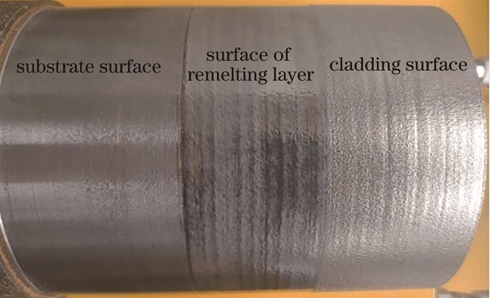
    Fig. 1. Macroscopic surface morphology of sample after cladding
    Surface topographies under ultra depth of field microscope. (a) High-speed laser cladding surface; (b) laser remelting surface
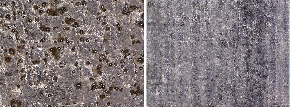
    Fig. 2. Surface topographies under ultra depth of field microscope. (a) High-speed laser cladding surface; (b) laser remelting surface
    XRD analysis of high-speed laser cladding and remelting layer surfaces
    Fig. 3. XRD analysis of high-speed laser cladding and remelting layer surfaces
    Microstructures of high-speed laser cladding and remelting layers. (a) Cross-section of cladding layer; (b) top area of cladding layer; (c) middle area of cladding layer; (d) bottom area of cladding layer; (e) cross-section of remelting layer; (f) top area of remelting layer; (g) middle area of remelting layer; (h) bottom area of remelting layer
    Fig. 4. Microstructures of high-speed laser cladding and remelting layers. (a) Cross-section of cladding layer; (b) top area of cladding layer; (c) middle area of cladding layer; (d) bottom area of cladding layer; (e) cross-section of remelting layer; (f) top area of remelting layer; (g) middle area of remelting layer; (h) bottom area of remelting layer
    Element distribution of coating
    Fig. 5. Element distribution of coating
    Hardness distribution of coating
    Fig. 6. Hardness distribution of coating
    Wear performances of sample. (a) Wear weight loss; (b) friction coefficient
    Fig. 7. Wear performances of sample. (a) Wear weight loss; (b) friction coefficient
    Wear morphologies under ultra depth of field microscope. (a) Substrate; (b) cladding layer; (c) remelting layer
    Fig. 8. Wear morphologies under ultra depth of field microscope. (a) Substrate; (b) cladding layer; (c) remelting layer
    ElementCSiMnVNiCuSP
    Mass fraction /%0.24-0.321.10-1.401.10-1.400.07-0.12≤0.3≤0.3≤0.04≤0.04
    Table 1. Compositions of 27SiMn steel
    ElementCSiMoCrBFe
    Mass fraction /%0.151.20.512.51.6Bal.
    Table 2. Main chemical compositions of Fe90 alloy powder
    ProcessP /WVf /(g·min-1Vs /(mm·s-1D /%
    High-speed laser cladding18006713681
    Remelting1800021281
    Table 3. Process parameters for test
    Zhihu Zhang, Wenlei Sun, Yong Huang, Jinduo Liu. Microstructures and Properties of Fe-Based Coating Prepared by High-Speed Laser Cladding and Remelting[J]. Laser & Optoelectronics Progress, 2021, 58(21): 2114009
    Download Citation