
Xiangyu Zeng, Yuqin Zhang, Manna Gu, Zijun Zhan, Ruirui Zhang, Yu Zhang, Rui Sun, Changwei He, Chunxiang Liu, Chuanfu Cheng. Arbitrary manipulations of focused higher-order Poincaré beams by a Fresnel zone metasurface with alternate binary geometric and propagation phases[J]. Photonics Research, 2022, 10(4): 1117
- Photonics Research
- Vol. 10, Issue 4, 1117 (2022)
Abstract
1. INTRODUCTION
Owing to the distinctive characteristics of inhomogeneous polarization distributions across transverse planes, vector beams (VBs) have attracted extensive attention over the past decade. Investigations of VBs have motivated discoveries of various interesting phenomena in the light field, such as the topological structures of polarization knots [1] and Möbius strips [2,3], and the sub-diffraction focusing spot [4,5], and have developed broad applications in classical areas, including high-resolution microscopy [6], precision metrology [7], laser fabrications [8–10], and classical communications [11]. Essentially, VBs are the non-separable superposition of spin angular momentum (SAM) and orbital angular momentum (OAM) eigenstates, similar to the local entanglement in a bipartite system [12,13] and given the term classically entangled light. In quantum mechanics, VBs have been used as a novel resource to encode rotational invariant qubits in alignment-free communication over a distance [14–16] and have been applied to teleportations [17], asymmetric quantum networks [18], and quantum walks [19].
Composed of artificial metallic or dielectric nanostructures of adjustable geometry, metasurfaces have a powerful ability to manipulate the light field in polarization, as well as phase and frequency degrees of freedom, and have been successfully engineered for versatile applications such as multifunctional metalenses [20–23], holography [24], quantum photon sources [25], and quantum entanglement of SAM and OAM [26]. As one of the most important applications of metasurfaces, the generations of VBs have been studied extensively, and various metasurfaces have enabled the manipulations of VBs [27–31]. The earlier metasurface designs concentrated on the generations of radially and azimuthally polarized vector beams (RPVBs and APVBs) by using the method of directly controlling the local polarization and phase of nanostructures [32–35], and this method is still in use at present [36,37], in spite of the inconvenient manipulation and simple type of generated VBs. In 2016, Yue
With the beam size to the subwavelength scale, tightly focused VBs have fascinating properties and unusual abilities of strong manipulations [39], and also they can provide the topological structure of light field in the focal region [2,40]. The generations of focused VBs have reasonably attracted particular interest, in which the two functionalities of focusing and manipulating the polarized vortices are integrated in a single metasurface [41–49]. Based on the earlier method of controlling the local polarization and phase, several theoretical designs of metasurfaces have been reported for super-resolution focusing of RPVBs and APVBs, notwithstanding lacking experimental demonstrations [42–44]; Ding
Sign up for Photonics Research TOC. Get the latest issue of Photonics Research delivered right to you!Sign up now
The difficulty in generating coaxial focused HOP beams of high qualities lies in the influence of different adverse backgrounds or hostile scatterings. Particularly, the residual incident spin component (ISC) can be uncontrollably focused as the bright spot at the center, coinciding with the dark cores of the vortices, and the quality of generated HOP beam may be vulnerably and obviously deteriorated; one of the probable originations for the residual ISC is the variant size and orientation of the nanostructures, which cause them to deviate from the homogeneous periodic boundary conditions and the ideal wave plates [51].
In this paper, we propose a novel plasmonic metasurface consisting of nanoslits arranged perpendicularly on the odd and even rings of Fresnel zone (FZ), denoted as FZ metasurfaces, to realize the manipulation of coaxial focused HOP beams. With the combined alternate binary geometric and propagation phases, the superposition of wavelets from the slits on two adjacent rings is designed to cancel the ISC through destructive interference and to focus the converted spin component (CSC) through constructive interference. By controlling the orientation of the nanoslits and adjusting the elliptical polarization of incident light, the superposition of two orthogonal OAM states of CSCs having topological charges of equal absolute value but opposite signs is realized. Correspondingly, the coaxial focused VB at an arbitrary point on the HOP sphere is generated. With the path-dependent propagation phase as the hyperbolic phase matched to the constructive interference, the metasurface design realizes accurate focusing, which differs from the previous work with the size-dependent resonant phase [45,46] (which also belongs to propagation phase) and polarization-dependent geometric phase for focusing [47]. Thus, our metasurfaces are composed of single-sized slits, avoiding the probable ISC due to the variant size of nanostructures. Besides, in contrast to the dielectric metasurfaces [52–54], the transmitted light field through metal slits undergoes the complete spin–orbit interaction [55], which provides the foundation for a clear cancellation of ISC contributing to the bright central peak. Additionally, the high accuracy of the focused ion beam (FIB) lithography allows the precise fabrications of the samples, avoiding to a good extent the fabrication-induced deviation of the nanostructures from the ideal wave plates. By taking these advantages of the metasurface designs, we demonstrate the generation of coaxial focused VBs of high quality. Here we first gave the theoretical analysis of the focused VB fields for the FZ metasurface design based on the Huygens–Fresnel principle and the transmittance property of the nanoslits; then by the simulations with finite-difference time domain (FDTD) method, we optimized the metasurfaces and demonstrated the generations of the focused HOP beams; the metasurfaces were designed for wavelength 632.8 nm and were also demonstrated to work at wavelengths 532 nm and 473 nm, respectively. Experimentally, we realized the HOP beams evolving on the equator and on the prime meridian of the HOP sphere with , 3 at the wavelength of 632.8 nm, 532 nm, and 473 nm, respectively, and we also realized the second- and third-order VBs on the equator of the HOP sphere at the wavelength of 632.8 nm. The generated HOP beams appeared to be of high quality and seemed to be among high levels of experimental focused VBs in our acquirable references. We expect that the method proposed in this paper will be of significance to related fields in classical and quantum physics.
2. PRINCIPLE ANALYSIS AND STRUCTURE DESIGN
Figure 1(a) is the schematic of the generation of the focused HOP beams by the FZ metasurface, which consists of nanoslits in a gold film on a fused silica substrate. A representative nanoslit occupying the substrate area of side-lengths and is shown in Fig. 1(a), panel i; the length and width of slit are and , respectively, and the orientation angle of the slit is the angle between the normal of the slit’s longer side and axis. The incident plane wave is elliptically polarized, and it contains components of right circular polarization (RCP) and left circular polarization (LCP) with the weights and , respectively. The output field includes the OAM states of LCP and RCP and , which are determined by the rotation order of the nanoslits, and the coaxial focused HOP beam of order is formed at the focal plane, with the dark core at the optical axis. The metasurface is designed for red light with wavelength 632.8 nm and is extended to green and blue light with wavelength 532 nm and 473 nm, respectively. Figure 1(a), panel ii shows the intensity patterns of generated VBs of order for demonstration at wavelengths of 473 nm, 532 nm, and 632.8 nm under the illuminating light of RCP (), horizontal linear polarization (), 45°-slanted linear polarization (), and arbitrary polarization , respectively. Figure 1(b) shows the scanning electron microscopy (SEM) image of a metasurface, and Fig. 1(c) shows an enlarged view. The nanoslits are arranged on the rings of FZ and grouped into odd and even rings, as labeled in green and in red, respectively, in Fig. 1(c). The nanoslits on the even rings of the FZs are perpendicular to those on the odd rings in the same radial line, producing the alternate binary geometric phases of 0 and . The orientation of the slit on the odd ring at azimuth is defined by , where is the orientation of initial slit at , and correspondingly, the slit orientation on the even ring is . The radius of the th ring sets the incremental path of the slits with wavelength and focal length [56], and it also introduces the alternate binary propagation phases of 0 and .
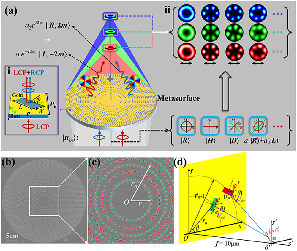
Figure 1.Schematic for generating the focused HOP beams via an FZ metasurface. (a) Basics for the generation of focused HOP beams. Upon illumination of incident beam of a wavelength
Figure 1(d) schematically demonstrates two slits on the odd and even rings, lying at the positions and with radii and , respectively. Generally, a thin slit acts as a local linear polarizer, with the transmitted direction perpendicular to its longer sides. Thus, the Jones matrix of the slit on the odd rings is , where is the rotation matrix and is the matrix for the polarizer with horizontal transmission. When the metasurface was illuminated by CP light , with helicity for LCP and RCP, respectively, and superscript denoting the transpose of the matrix, the transmitted fields of slits on the odd and even rings are calculated as
First, we consider the wave field produced by the odd rings in the polar coordinates on the focal plane. Such a wave field can be taken as the discrete sum of wavelet fields diffracted from the slits, but for more general expression, it is replaced by the integral over the metasurface. Based on the vector-form Huygens–Fresnel principle [57], it is written as
The optical path for an even ring has an increment of relative to its adjacent odd ring, so a propagation phase difference is introduced. Based on Eqs. (1) and (3), by adding and , we obtain the focused field under CP illumination:
When the illuminating light is generalized to an arbitrary elliptical polarization, it can be represented geometrically by a point on the conventional Poincaré sphere (PS) with spherical coordinates () and can be written as the superposition of RCP and LCP lights:
is related to by
The lower limit was neglected owing to the insignificance of in comparison with in Eq. (7). Equation (6) indicates that the focused HOP beam is formed, which is the contribution of the two CSCs. The beam was radially modulated by the hypergeometric function and is called a vector hypergeometric beam. By controlling the parameters , and of the metasurface and the incident light, the polarization state of the VB at point () on the HOP sphere of order can be manipulated arbitrarily. From Eq. (6), the relation was obtained for mapping the incident light on PS to VBs on the HOP sphere. Interestingly, when the incident light went from north to south poles on the PS, the generated VB moved oppositely from the south to the north poles on the HOP sphere.
3. SIMULATION RESULTS
Using FDTD (Lumerical Solutions) software, the simulations of the focused RPVB and APVB produced by the metasurface sample with parameters and were first performed to demonstrate the focusing effect of the metasurface. The optimized slit dimension is and , and the focal length is set at for wavelength of . The number of rings with the diameter of metasurface 32.0 μm. Figure 2(a) shows the schematic demonstration. Panels i and ii in Fig. 2(b) show the total intensity patterns on the plane and the focal plane under the -polarized incident light, respectively, at wavelength 632.8 nm, and panel iii in Fig. 2(b) shows the curves of the total and component intensities along the direction. The results indicate that a strong longitudinal component field was obtained, where the intensity curve of exhibited a sharp focused profile with full width at half-maximum (FWHM) of . The patterns and curves for APVB in panels iv–vi in Figs. 2(b) demonstrate that the beam has a profile with a hollow core with FWHM (the inner FWHM) of under the -polarized incident light. These results demonstrate that tight focusing of the VBs was achieved. The transmitted efficiency for the powers of the transmitted field from the slit at different wavelengths was simulated under periodic boundary condition with illumination of LCP; the power values were the sum of the ISC and the CSC averaged over the substrate area , and the data at the distance of a wavelength behind the slit are shown in Fig. 2(c). Therein the power ratios of ISC and CSC to the transmitted power are also shown, respectively. The phases for an individual slit were also simulated, and the on-axis data at a distance of wavelength are shown in Fig. 2(c). The transmitted efficiency is 9.45% for the main wavelength 632.8 nm, 0.87% for the wavelength 532 nm, and 1.76% for 473 nm, respectively. As might be understood, one of the reasons for the limited efficiency is the small aspect ratio of the nanoslit for the occupied substrate area. For some application scenarios, particularly with laser sources of higher power but requirement of high beam quality, the limited efficiency might be acceptable. Panels i–iii in Fig. 2(d) show the simulated intensity profiles in the plane at the wavelengths of 632.8 nm, 532 nm, and 473 nm, for the metasurface designed to generate the focused RPVB. The corresponding focal lengths are , 14.2 μm, and 17.6 μm, respectively. Next, for the metasurface with and under the illumination of elliptically polarized lights at the designed wavelength of 632.8 nm, the weights squared for the CSCs and were extracted from the simulation results and plotted versus coordinate 2Θ of the incident light on prime meridian on the PS, as represented by scattered stars of Fig. 2(e), respectively. The corresponding curves are plotted based on Eq. (6). The cross similarity of the curves in Fig. 2(e) for VBs and in the inset for the incident light validates the map of point () on PS to point on the HOP sphere. Figure 2(e) also presents the intensity patterns of the -polarized components at five values on the top row, and the blurred lobes in the two patterns for and intuitively reflect the elliptical polarization states of the generated VBs. In addition, in the FDTD simulations, many sophisticated optimizations were performed for the output field of each experimental sample before fabrication.
![]()
Figure 2.Numerical simulations for the generation of the focused HOP beams. (a) Schematic and (b) simulation results of the focused RPVB and APVB. The focused solid spot with an approximately
To analyze the broadband properties and the chromatic dispersion, we further performed the broadband simulations of the APVBs with FDTD, and the total intensity images of beams for 14 wavelengths in the range from 450 nm to 650 nm are shown in Fig. 3(a), where the images are in a unified color bar. These images demonstrate that the HOP beams can be achieved in the broadband. The focal lengths corresponding to these were extracted, as shown in Fig. 3(b), which appears to be approximately linearly decreased in wavelength range under consideration, indicating the chromatic dispersion of the metasurface. The FWHMs of the hollow cores in the total intensity profiles for the APVBs of different wavelengths at the focal planes were also extracted, and they are shown in blue curve in Fig. 3(b); on the whole, the FWHM as the multiplier of wavelength decreases with the wavelength, with the value for the main wavelength 632.8 nm being . The variation of the tightly focused VBs, including the beam size and the corresponding divergence, with observation distance away from focal plane, is of importance in focusing engineering [59,60] and in light field topology [2,40]. The variation of tightly focused APVBs may be analyzed through that of the FWHMs [48,61]. To this end, we extracted the FWHMs of the APVBs at seven distances near the focal planes for the wavelengths 632.8 nm, 532 nm, and 473 nm, respectively, and the results are presented in Fig. 3(c). It is seen that the FWHM (relative to wavelength) is smaller for larger wavelength of light; this is related to the shorter focal length and then the larger NA of the metasurface. Moreover, with the unobvious maximum at the focal plane, the variation of FWHM for the wavelength 632.8 nm indicates that the generated beam behaves the same as the general tightly focused VBs [48,62,63], which has been demonstrated to diverge quickly outside the depth of focus of several wavelengths [63] at large NA. The variations of FWHM for other two wavelengths appear to be more complicated [48], presumably because of the smaller NA and the non-specific wavelength optimization in the metasurface design.
![]()
Figure 3.(a) Intensity patterns of APVB on the focal plane at 14 different wavelengths between 450 and 650 nm. All the patterns are in a unified color bar. (b) The focal length (red stars) and the inner FWHM (blue triangles) at different wavelengths. (c) The FWHM of the simulated APVB along the optical axis with wavelengths
4. EXPERIMENTAL SETUP AND RESULTS
Figure 4(a) illustrates the optical setup for generating the focused HOP beams of arbitrary polarization states. Three lasers of wavelengths 632.8 nm, 532 nm, and 473 nm were used as the light sources, respectively. The elliptically polarized light was obtained after the half-wave plate (HWP) and quarter-wave plate (QWP) to illuminate the sample. The focused HOP beam behind the sample was captured by the MO, and the polarization component patterns were imaged using Andor’s Zyla 5.5 sCMOS camera. Four samples, i.e., , and , with , and 5/2, respectively, and , were fabricated on the Au films with 200 nm thickness over silica substrates. Here, the superscript denotes . SEM images of samples and are shown in Figs. 4(b) and 4(c), respectively. In the fabrication, the Au films were deposited on substrate by use of magnetron sputtering under the pressure of with a deposition rate of 1 nm/s. Then the slits of the designed metasurfaces were etched in the Au film with the FIB system (FEI Helios G4 UX) at the acceleration voltage of 30 kV and beam current of 93 pA. By adjusting the incident elliptical polarization, the samples can produce VBs corresponding to any point on the HOP sphere of order .
![]()
Figure 4.(a) Schematic diagram of the experimental setup. HWP, half-wave plate; QWP, quarter-wave plate; A, attenuator; MO, microscope objective (
![]()
Figure 5.Experimental results of the HOP beams of order
In Fig. 5(b), the experimental intensity patterns of the VBs produced by sample are presented at the wavelength of 632.8 nm with the polarization angle of incident light being horizontal (), diagonal (), vertical (), and antidiagonal (), respectively. The patterns from the top to bottom rows are the VBs of radial, 135º-slanted, azimuthal, and 45º-slanted polarization, corresponding to the four points in clockwise order from A to D on the equator of the HOP sphere with , respectively, which are in mapping correlation to the points from a to d in opposite directions on the equator on PS, as illustrated in Fig. 5(a). The polarization states are schematically indicated by arrows overlaid on the doughnut patterns.
The optical mechanism correlating the incident light to the VB is pictorially depicted in Fig. 4(d); the left horizontal slit and right vertical slit constitute the initial double slits located on odd and even rings of sample , respectively. Remembering that the transmitted field of the slit is polarized perpendicularly to its longer side, under the -polarized incident light, the right slit can excite the transmitted field while the left cannot, with the superposed field being that of the former, as demonstrated in Fig. 4(d), panel i. In contrast, under the -polarized incident light, the superposed field is that of the latter, as shown in Fig. 4(d), panel iii. When the polarization direction of incident light is rotated counterclockwise from 0 to , the components and of excite and of the transmitted field through the right vertical slit and left horizontal slit, as demonstrated in Fig. 4(d), panel ii, the inverse direction in is consistent with the optical path increment , and the superposed field of double slits is polarized at angle .
Fundamentally, when sample is illuminated by the incident light polarizing in angle to the axis with corresponding longitude , the included RCP and LCP were transformed into vortices and , respectively. Thus, the superposed VB has the linear polarization state with longitude on the equator. This finding demonstrates that when the incident polarization goes along the equator on the PS, the VB goes opposite to the HOP sphere, as demonstrated in Fig. 5(a). Figures 5(c) and 5(d) show the similar experimental results to those in Fig. 5(b) for sample but under illuminating light with the wavelength of 532 nm and 473 nm, respectively.
Figure 5(e) shows the intensity patterns of VBs also produced by at nine latitude points labeled by I (south pole) to IX (north pole) on the prime meridian of the HOP sphere under the illuminations of the three wavelengths, corresponding to the polarization states of the incident light going from point i (north pole) to ix (south pole) on the prime meridian of PS, with the latitudes varying from 0 to in intervals of , as indicated in Fig. 5(a). The patterns of each wavelength show that, when the polarization states of the VBs move from the equator to the poles, the orientations of the lobes in the -component patterns remain unchanged, but their boundaries become blurred.
Figure 6(a) shows the experimentally measured patterns of VBs on the equator of the HOP with orders , 3, and 5 produced by samples , and , in rows from 1 to 3, respectively. The patterns in the left column are the total intensity doughnut of the VBs at point A on the corresponding HOP sphere. The red double-sided arrows on the top title row represent incident polarizations, i.e., , and from left to right, respectively. The gray hollow arrows mark the orientation of the lobes. Each pattern of polarization component has lobes, which manifests the azimuthal interference fringes of the -polarized vortices and in the azimuthal cycle . When the incident linear polarization rotates to angle , in the pattern of the corresponding VB, the lobe marked with the hollow arrow rotates to the angle .
![]()
Figure 6.Experimental intensity patterns produced by samples
For further demonstrations, Fig. 6(b1) shows the intensity patterns of the HOP beams produced by on the prime meridian at wavelength of 632.8 nm, still at the nine points shown in Fig. 5(a), but on the sphere of . The incident polarization ellipse is plotted in the upper-left corner of each pattern. Figure 6(b2) shows the given intensity patterns of the nine points for wavelength of 532 nm and 473 nm, and elliptical and round arrows in the title row label the incident polarizations. Overall, all the experimental patterns of the focused HOP beams generated with the FZ samples were of higher quality, and the implementations were feasible and convenient.
5. DISCUSSION
Though there is noticeable improved quality of the above-focused HOP beams, to introduce a quantitative evaluation is necessary for beams to be compared with those produced by the previous methods. To this end, we choose the commonly used vector quality factor (VQF), which is defined as concurrence (also denoted by C) for quality description of the general VBs [64], and it was first proposed as the quality measure of VBs formed by two cylindrical vector vortex modes [65]. It is defined as [64,65]
We take the HOP beams of order 2 for the main wavelength 632.8 nm as the example to look at the improvement of the beam quality with the method in this paper. We first calculated the theoretical VQF on the prime meridian of the sphere [13,64], which is taken as the standard VQF, and it is given in the red solid curve in Fig. 7(a). Correspondingly, using FDTD, we also performed the simulations of the HOP beams produced by the corresponding metasurface sample designed with the method of this paper. Nine beams at the corresponding latitude points on the prime meridian from the north to south pole in equal latitude-intervals were simulated, and then the VQF of the beams was calculated based on Eqs. (9) and (10), given in blue stars in Fig. 7(a). For comparison, the metasurface sample was designed as the one by the state-of-the-art method, also to produce the corresponding HOP beams of order 2, and it was composed of single slits rather than the orthogonal slit-pairs, with the same slit size of ; the slits were arranged in grids along and axes [29], the geometric phase of the slit was used simultaneously for both the hyperbolic phase of lens and the spiral phase of vortex, and the sample was of the same dimension as above metasurface of this paper. The corresponding nine beams were also simulated, and the obtained VQF is shown in green triangle in Fig. 7(a). The deviations of the VQF values for the two samples from the theoretical values are also shown in green triangles in Fig. 7(a), demonstrating that the quality of the HOP beams by the method of the paper is improved. For intuitive visualizations, the simulated intensity images of x-polarized component at for two samples are shown in Fig. 7(a).
![]()
Figure 7.VQF as a function of the parameters (a)
To understand the influence of fabrication imperfections such as the size and rounded corner of the slits on the quality of the generated beams, we conducted the FDTD simulations accordingly on the HOP beams of order 2 produced by seven FZ metasurfaces () of different slit sizes, while each of metasurfaces was composed of identical slits. The slits took the same length of , and the width varied from 90 nm to 150 nm, with increment of 10 nm for the metasurfaces in slit width order. Since the VQF of the produced HOP beams at the point with the latitude on the prime meridian appeared to deviate moderately from the standard beams, we calculated the VQF of these beams at this point, and it is shown in round dots in Fig. 7(b). It demonstrates that the metasurface with the larger width will to some degree lower the quality of the generated HOP beams. Further, we replace the rectangle slit with an elliptical slit, with the major axis 300 nm and minor axis 110 nm for an area approximately equal to the original slit (the rectangle of ), to check the influence of rounded corners of the slits, and again the HOP beams of order 2 produced by the metasurface of the elliptical slits were simulated. We obtained the VQF and had the largest difference 0.171 from standard value at the north pole, in contrast to the largest difference 0.181 also at the north pole for our metasurface of rectangle slits. This indicates that the round corner of the slits does not have much adverse effects on the quality of the generated VBs for the plamonic metasurfaces. On the whole, though the size errors in fabricating the metasurfaces may decrease to some degree the quality of the VBs, within the easily feasible fabricating accuracy of 10 nm, and considering the non-adverse influence of the round corner, the deterioration of the beam quality due to the imperfections in fabricating the plasmonic metasurfaces can be well controlled.
6. CONCLUSION
In summary, we experimentally demonstrate FZ metasurfaces to manipulate broadband coaxial focused HOP beams, realizing the arbitrary transformation from incident polarization at () on PS to VB at () on the HOP sphere. The slits on the odd and even rings set the alternate binary geometric and propagation phases, with the hyperbolic phase being exactly matched. The focusing of the CSCs was realized through a constructive interference, avoiding the geometric-phase-related diverging component. Although the plasmonic metasurface is usually thought to have a low transmittance, all transmitted light through metallic slits completely undergoes spin–orbit interactions [55], and the metasurface inherently overcomes the bright central peak due to residual ISC [53,54] existing in the dielectric metasurface [54]. Therefore, this characteristic of plasmonic metasurfaces is important for achieving coaxial focused HOP beams of high quality, of which the dark cores are vulnerable even to small background light, and for other applications with requirements of high-quality light manipulation. Besides, the focused HOP beams generated under incident light of different wavelengths have been obtained at a different focal plane. It is envisioned that, by introducing techniques eliminating the chromatic aberration in metalens for the focusing manipulation such as the integrated-resonant units [66,67] and the combined C-shaped units [68], the potential achromatic operation for generating real broadband HOP beams is hopeful to be realized. Lastly, our metasurface design provides a novel method for manipulating focused HOP beams flexibly and feasibly and proves important and useful for integrated devices in various conventional and quantum applications.
References
[1] E. Pisanty, G. J. Machado, V. Vicuña-Hernández, A. Picón, A. Celi, J. P. Torres, M. Lewenstein. Knotting fractional-order knots with the polarization state of light. Nat. Photonics, 13, 569-574(2019).
[2] T. Bauer, P. Banzer, E. Karimi, S. Orlov, A. Rubano, L. Marrucci, E. Santamato, R. W. Boyd, G. Leuchs. Observation of optical polarization Möbius strips. Science, 347, 964-966(2015).
[3] P. Huo, S. Zhang, Q. Fan, Y. Lu, T. Xu. Photonic spin-controlled generation and transformation of 3D optical polarization topologies enabled by all-dielectric metasurfaces. Nanoscale, 11, 10646-10654(2019).
[4] H. Wang, L. Shi, B. Lukyanchuk, C. Sheppard, C. T. Chong. Creation of a needle of longitudinally polarized light in vacuum using binary optics. Nat. Photonics, 2, 501-505(2008).
[5] E. T. Rogers, J. Lindberg, T. Roy, S. Savo, J. E. Chad, M. R. Dennis, N. I. Zheludev. A super-oscillatory lens optical microscope for subwavelength imaging. Nat. Mater., 11, 432-435(2012).
[6] X. Xie, Y. Chen, K. Yang, J. Zhou. Harnessing the point-spread function for high-resolution far-field optical microscopy. Phys. Rev. Lett., 113, 263901(2014).
[7] V. D’ambrosio, N. Spagnolo, L. Del Re, S. Slussarenko, Y. Li, L. C. Kwek, L. Marrucci, S. P. Walborn, L. Aolita, F. Sciarrino. Photonic polarization gears for ultra-sensitive angular measurements. Nat. Commun., 4, 2432(2013).
[8] J. J. Nivas, S. He, A. Rubano, A. Vecchione, D. Paparo, L. Marrucci, R. Bruzzese, S. Amoruso. Direct femtosecond laser surface structuring with optical vortex beams generated by a q-plate. Sci. Rep., 5, 17929(2015).
[9] T. Omatsu, K. Miyamoto, K. Toyoda, R. Morita, Y. Arita, K. Dholakia. A new twist for materials science: the formation of chiral structures using the angular momentum of light. Adv. Opt. Mater., 7, 1801672(2019).
[10] J. J. Nivas, E. Allahyari, F. Cardano, A. Rubano, R. Fittipaldi, A. Vecchione, D. Paparo, L. Marrucci, R. Bruzzese, S. Amoruso. Vector vortex beams generated by q-plates as a versatile route to direct fs laser surface structuring. Appl. Surf. Sci., 471, 1028-1033(2019).
[11] G. Milione, M. P. Lavery, H. Huang, Y. Ren, G. Xie, T. A. Nguyen, E. Karimi, L. Marrucci, D. A. Nolan, R. R. Alfano, A. E. Willner. 4 × 20 Gbit/s mode division multiplexing over free space using vector modes and a q-plate mode (de)multiplexer. Opt. Lett., 40, 1980-1983(2015).
[12] V. D’Ambrosio, G. Carvacho, F. Graffitti, C. Vitelli, B. Piccirillo, L. Marrucci, F. Sciarrino. Entangled vector vortex beams. Phys. Rev. A, 94, 030304(2016).
[13] B. Zhao, X. B. Hu, V. Rodríguez-Fajardo, A. Forbes, W. Gao, Z. H. Zhu, C. Rosales-Guzmán. Determining the non-separability of vector modes with digital micromirror devices. Appl. Phys. Lett., 116, 091101(2020).
[14] V. D’ambrosio, E. Nagali, S. P. Walborn, L. Aolita, S. Slussarenko, L. Marrucci, F. Sciarrino. Complete experimental toolbox for alignment-free quantum communication. Nat. Commun., 3, 961(2012).
[15] G. Vallone, V. D’Ambrosio, A. Sponselli, S. Slussarenko, L. Marrucci, F. Sciarrino, P. Villoresi. Free-space quantum key distribution by rotation-invariant twisted photons. Phys. Rev. Lett., 113, 060503(2014).
[16] V. Parigi, V. D’Ambrosio, C. Arnold, L. Marrucci, F. Sciarrino, J. Laurat. Storage and retrieval of vector beams of light in a multiple-degree-of-freedom quantum memory. Nat. Commun., 6, 7706(2015).
[17] T. M. Graham, H. J. Bernstein, T. C. Wei, M. Junge, P. G. Kwiat. Superdense teleportation using hyperentangled photons. Nat. Commun., 6, 7185(2015).
[18] E. Nagali, F. Sciarrino. Generation of hybrid polarization-orbital angular momentum entangled states. Opt. Express, 18, 18243-18248(2010).
[19] F. Cardano, F. Massa, H. Qassim, E. Karimi, S. Slussarenko, D. Paparo, C. de. Lisio, F. Sciarrino, E. Santamato, R. W. Boyd, L. Marrucci. Quantum walks andwavepacket dynamics on a lattice with twisted photons. Sci. Adv., 1, e1500087(2015).
[20] M. Khorasaninejad, F. Capasso. Metalenses: versatile multifunctional photonic components. Science, 358, eaam8100(2017).
[21] Z. Shen, S. Zhou, X. Li, S. Ge, P. Chen, W. Hu, Y. Lu. Liquid crystal integrated metalens with tunable chromatic aberration. Adv. Photon., 2, 036002(2020).
[22] W. T. Chen, M. Khorasaninejad, A. Y. Zhu, J. Oh, R. C. Devlin, A. Zaidi, F. Capasso. Generation of wavelength-independent subwavelength Bessel beams using metasurfaces. Light Sci. Appl., 6, e16259(2017).
[23] E. Arbabi, A. Arbabi, S. M. Kamali, Y. Horie, M. Faraji-Dana, A. Faraon. MEMS-tunable dielectric metasurface lens. Nat. Commun., 9, 812(2018).
[24] Z. L. Deng, J. H. Deng, X. Zhuang, S. Wang, K. F. Li, Y. Wang, Y. H. Chi, X. Ye, J. Xu, G. P. Wang, R. K. Zhao, X. L. Wang, Y. Y. Cao, X. Cheng, G. X. Li, X. P. Li. Diatomic metasurface for vectorial holography. Nano Lett., 18, 2885-2892(2018).
[25] L. Li, Z. Liu, X. Ren, S. Wang, V. C. Su, M. K. Chen, C. H. Chu, H. Y. Kuo, B. Liu, W. Zang, G. Guo, L. Zhang, Z. Wang, S. Zhu, D. P. Tsai. Metalens-array-based high-dimensional and multiphoton quantum source. Science, 368, 1487-1490(2020).
[26] T. Stav, A. Faerman, E. Maguid, D. Oren, V. Kleiner, E. Hasman, M. Segev. Quantum entanglement of the spin and orbital angular momentum of photons using metamaterials. Science, 361, 1101-1104(2018).
[27] R. C. Devlin, A. Ambrosio, N. A. Rubin, J. B. Mueller, F. Capasso. Arbitrary spin-to-orbital angular momentum conversion of light. Science, 358, 896-901(2017).
[28] F. Yue, D. Wen, J. Xin, B. D. Gerardot, J. Li, X. Chen. Vector vortex beam generation with a single plasmonic metasurface. ACS Photon., 3, 1558-1563(2016).
[29] F. Yue, D. Wen, C. Zhang, B. D. Gerardot, W. Wang, S. Zhang, X. Chen. Multichannel polarization-controllable superpositions of orbital angular momentum states. Adv. Mater., 29, 1603838(2017).
[30] C. Zhang, F. Yue, D. Wen, M. Chen, Z. Zhang, W. Wang, X. Chen. Multichannel metasurface for simultaneous control of holograms and twisted light beams. ACS Photon., 4, 1906-1912(2017).
[31] Z. H. Jiang, L. Kang, T. Yue, H. X. Xu, Y. Yang, Z. Jin, C. Yu, W. Hong, D. H. Werner, C. W. Qiu. A single noninterleaved metasurface for high-capacity and flexible mode multiplexing of higher-order Poincaré sphere beams. Adv. Mater., 32, 1903983(2020).
[32] Z. Zhao, J. Wang, S. Li, A. E. Willner. Metamaterials-based broadband generation of orbital angular momentum carrying vector beams. Opt. Lett., 38, 932-934(2013).
[33] S. Wang, D. C. Abeysinghe, Q. Zhan. Generation of vectorial optical fields with slotantenna-based metasurface. Opt. Lett., 40, 4711-4714(2015).
[34] P. Yu, S. Chen, J. Li, H. Cheng, Z. Li, W. Liu, B. Xie, Z. Liu, J. Tian. Generation of vector beams with arbitrary spatial variation of phase and linear polarization using plasmonic metasurfaces. Opt. Lett., 40, 3229-3232(2015).
[35] Q. Guo, C. Schlickriede, D. Wang, H. Liu, Y. Xiang, T. Zentgraf, S. Zhang. Manipulation of vector beams polarization with geometric metasurfaces. Opt. Express, 25, 14300-14307(2017).
[36] Y. Zhang, R. Zhang, X. Li, L. Ma, C. Liu, C. He, C. Cheng. Radially polarized plasmonic vector vortex generated by a metasurface spiral in gold film. Opt. Express, 25, 32150-32160(2017).
[37] T. Li, Z. Li, S. Chen, L. Zhou, N. Zhang, X. Wei, G. Song, Q. Gan, Y. Xu. Efficient generation of broadband short-wave infrared vector beams with arbitrary polarization. Appl. Phys. Lett., 114, 021107(2019).
[38] G. Milione, H. I. Sztul, D. A. Nolan, R. R. Alfano. Higher-order Poincaré sphere, Stokes parameters, and the angular momentum of light. Phys. Rev. Lett., 107, 053601(2011).
[39] J. Ni, C. Huang, L. M. Zhou, M. Gu, Q. Song, Y. Kivshar, C. W. Qiu. Multidimensional phase singularities in nanophotonics. Science, 374, eabj0039(2021).
[40] X. Guo, P. Li, J. Zhong, S. Liu, B. Wei, W. Zhu, S. Qi, H. Cheng, J. Zhao. Tying polarization-switchable optical vortex knots and links via holographic all-dielectric metasurface. Laser Photon. Rev., 14, 1900366(2020).
[41] A. Arbabi, Y. Horie, M. Bagheri, A. Faraon. Dielectric metasurfaces for complete control of phase and polarization with subwavelength spatial resolution and high transmission. Nat. Nanotechnol., 10, 937-943(2015).
[42] F. Zhang, H. Yu, J. Fang, M. Zhang, S. Chen, J. Wang, A. He, J. Chen. Efficient generation and tight focusing of radially polarized beam from linearly polarized beam with all-dielectric metasurface. Opt. Express, 24, 6656-6664(2016).
[43] R. Zuo, W. Liu, H. Cheng, S. Chen, J. Tian. Breaking the diffraction limit with radially polarized light based on dielectric metalenses. Adv. Opt. Mater., 6, 1800795(2018).
[44] Y. Li, L. Cao, Z. Wen, C. Qin, J. Yang, Z. Zhang, G. Liang, Z. Shang, K. Zhang, S. Zhang, L. Dai, G. Chen. Broadband quarter-wave birefringent meta-mirrors for generating sub-diffraction vector fields. Opt. Lett., 44, 110-113(2019).
[45] F. Ding, Y. Chen, Y. Yang, S. I. Bozhevolnyi. Multifunctional metamirrors for broadband focused vector-beam generation. Adv. Opt. Mater., 7, 1900724(2019).
[46] F. Ding, Y. Chen, S. I. Bozhevolnyi. Focused vortex-beam generation using gap-surface plasmon metasurfaces. Nanophotonics, 9, 371-378(2020).
[47] E. Wang, L. Shi, J. Niu, Y. Hua, H. Li, X. Zhu, C. Xie, T. Ye. Multichannel spatially nonhomogeneous focused vector vortex beams for quantum experiments. Adv. Opt. Mater., 7, 1801415(2019).
[48] Z. Wu, F. Dong, S. Zhang, S. Yan, G. Liang, Z. Zhang, Z. Wen, G. Chen, L. Dai, W. Chu. Broadband dielectric metalens for polarization manipulating and superoscillation focusing of visible light. ACS Photon., 7, 180-189(2019).
[49] M. Liu, P. Huo, W. Zhu, C. Zhang, S. Zhang, M. Song, S. Zhang, Q. Zhou, L. Chen, H. J. Lezec, A. Agrawal, Y. Lu, T. Xu. Broadband generation of perfect Poincaré beams via dielectric spin-multiplexed metasurface. Nat. Commun., 12, 2230(2021).
[50] Y. Bao, J. Ni, C. W. Qiu. A minimalist single-layer metasurface for arbitrary and full control of vector vortex beams. Adv. Mater., 32, 1905659(2020).
[51] R. Fu, L. Deng, Z. Guan, S. Chang, J. Tao, Z. Li, G. Zheng. Zero-order-free meta-holograms in a broadband visible range. Photon. Res., 8, 723-728(2020).
[52] R. Zhao, B. Sain, Q. Wei, C. Tang, X. Li, T. Weiss, L. Huang, Y. Wang, T. Zentgraf. Multichannel vectorial holographic display and encryption. Light Sci. Appl., 7, 95(2018).
[53] J. P. B. Mueller, N. A. Rubin, R. C. Devlin, B. Groever, F. Capasso. Metasurface polarization optics: independent phase control of arbitrary orthogonal states of polarization. Phys. Rev. Lett., 118, 113901(2017).
[54] K. T. Lim, H. Liu, Y. Liu, J. K. Yang. Holographic color prints for enhanced optical security by combined phase and amplitude control. Nat. Commun., 10, 25(2019).
[55] K. Y. Bliokh, F. J. Rodríguez-Fortuño, F. Nori, A. V. Zayats. Spin–orbit interactions of light. Nat. Photonics, 9, 796-808(2015).
[56] D. Attwood. Soft X-Rays and Extreme Ultraviolet Radiation: Principles and Applications(2000).
[57] T. V. Teperik, A. Archambault, F. Marquier, J. J. Greffet. Huygens-Fresnel principle for surface plasmons. Opt. Express, 17, 17483-17490(2009).
[58] Q. Cao, J. Jahns. Modified Fresnel zone plates that produce sharp Gaussian focal spots. J. Opt. Soc. Am. A, 20, 1576-1581(2003).
[59] Q. Zhan. Cylindrical vector beams: from mathematical concepts to applications. Adv. Opt. Photon., 1, 1-57(2009).
[60] X. Wang, L. Gong, Z. Zhu, B. Gu, Q. Zhan. Creation of identical multiple focal spots with three-dimensional arbitrary shifting. Opt. Express, 25, 17737-17745(2017).
[61] J. Gao, S. Yan, Y. Zhou, G. Liang, Z. Zhang, Z. Wen, G. Chen. Polarization-conversion microscropy for imaging vectorial polarization distribution in focused light. Optica, 8, 984-994(2021).
[62] Y. Kozawa, S. Sato. Focusing property of a double-ring-shaped radially polarized beam. Opt. Lett., 31, 820-822(2006).
[63] B. Tian, J. Pu. Tight focusing of a double-ring-shaped, azimuthally polarized beam. Opt. Lett., 36, 2014-2016(2011).
[64] A. Selyem, C. Rosales-Guzmán, S. Croke, A. Forbes, S. Franke-Arnold. Basis-independent tomography and nonseparability witnesses of pure complex vectorial light fields by Stokes projections. Phys. Rev. A, 100, 063842(2019).
[65] B. Ndagand, H. Sroor, M. Mclaren, C. Rosales-Guzmán, A. Forbes. Beam quality measure for vector beams. Opt. Lett., 41, 3407-3410(2016).
[66] S. Wang, P. C. Wu, V. C. Su, Y. C. Lai, C. H. Chu, J. W. Chen, S. H. Lu, J. Chen, B. Xu, C. H. Kuan. Broadband achromatic optical metasurface devices. Nat. Commun., 8, 187(2017).
[67] H.-H. Hsiao, Y. H. Chen, R. J. Lin, P. C. Wu, S. Wang, B. H. Chen, D. P. Tsai. Integrated resonant unit of metasurfaces for broadband efficiency and phase manipulation. Adv. Opt. Mater., 6, 1800031(2018).
[68] Q. Cheng, M. Ma, D. Yu, Z. Shen, J. Xie, J. Wang, N. Xu, H. Guo, W. Hu, S. Wang. Broadband achromatic metalens in terahertz regime. Sci. Bull., 64, 1525-1531(2019).

Set citation alerts for the article
Please enter your email address
© Copyright 2018-2021 | Chinese Laser Press. All Rights Reserved 沪ICP备15018463号-20