1State Key Laboratory for Modern Optical Instrumentation, Center for Optical & Electromagnetic Research, College of Optical Science and Engineering, International Research Center for Advanced Photonics, Zhejiang University, Zijingang Campus, Hangzhou 310058, China
2ZJU-Hangzhou Global Scientific and Technological Innovation Center, Hangzhou 311200, China
3Ningbo Research Institute, Zhejiang University, Ningbo 315100, China
A compact on-chip reconfigurable multichannel amplitude equalizer based on cascaded elliptical microrings is proposed and demonstrated experimentally. With the optimized structure of the elliptical microring with adiabatically varied radii/widths, the average excess loss for each channel in the initialized state is measured to be less than 0.5 dB, while the attenuation dynamic range can be over 20 dB. Flexible tunability through the overlapping of the resonance peaks of adjacent wavelength-channels enables even higher attenuation dynamic ranges up to 50 dB. Leveraging the thermo-optic effect and fine wavelength-tuning linearity, precise tuning of the resonance peak can be implemented, enabling dynamic power equalization of each wavelength-channel in wavelength-division-multiplexing (WDM) systems and optical frequency combs. The proposed architecture exhibits excellent scalability, which can facilitate the development of long-haul optical transport networks and high-capacity neuromorphic computing systems, while improving the overall performance of optical signals in WDM-related systems.
1. INTRODUCTION
Nowadays, the increasing data transmission capacity places higher demands on the development of optical communication systems, especially wavelength-division-multiplexing (WDM) networks [1,2]. Multiplexed signals in WDM systems need to be amplified by the erbium-doped fiber amplifier (EDFA) to travel longer distances [3]. While transmitting multichannel WDM optical signals, it is necessary to maintain flat spectral characteristics through power monitoring and dynamic amplitude equalization. The reconfigurable amplitude equalizer is widely used for the power equalization of WDM channels in optical transmission systems. The power uniformity of multichannel optical signals is important to improve the optical signal-to-noise ratio (OSNR) and bit error rate (BER) in long-haul transmission systems. Furthermore, for the optical frequency combs (OFCs) that have been under extensive investigation, the utilization of multichannel amplitude equalizers for flexible power equalization of each comb line makes them suitable as light sources in optical computing and neuromorphic photonics without the need for additional variable optical attenuators (VOAs) in each channel [4–6]. Meanwhile, considering the multiple-source microwave photonic filters in the field of microwave photonics, the output powers of different wavelength sources can be adjusted by amplitude equalizers to obtain a specific impulse response windowing, which can thus realize the apodization of the time response of the filter and reconfiguration of the filter transfer function shape [7–9].
The amplitude equalization mainly depends on VOAs, which are considered as key components. Over the past few years, several types of VOAs based on bulk components have been commercially available, including microelectromechanical systems (MEMS) [10,11] and liquid crystals (LCs) [12–14]. However, the mechanical stability is still to be improved further, and the response is relatively slow. Furthermore, they usually have very large footprints and are hard to integrate with other components conveniently on the same photonic chip. Alternatively, another implementation scheme for VOAs is using photonic integrated circuit (PIC) technology. Recently, some progress has been achieved by using polymer optical waveguides [15–18] because polymer usually has a large thermo-optic coefficient, which is helpful to lower the power consumption. However, the material stability makes it unavailable yet for practical applications with high temperature.
On the other hand, silicon photonics has shown great potential for PICs including VOAs because of its unique advantages of high integration density and complementary-metal-oxide-semiconductor (CMOS) compatibility [19,20]. It is very promising to realize large-scale PICs for optical processing [21,22]. Previously, excellent VOAs have been achieved by using the free-carrier absorption effect in silicon photonic waveguides with PN junctions [23–27]. In this case, the VOAs naturally have a fast response at the nanosecond scale, while the devices are typically millimeter-long due to the weak modulation effect. Instead, silicon has a high thermo-optical coefficient of and high thermal conductivity, which makes it suitable for building thermally reconfigurable components with compact footprints [28–31]. For example, VOAs can be realized by utilizing thermo-optic Mach–Zehnder interferometers (MZIs) [28–33]. Considering the applications in WDM systems with multiple channels, reconfigurable amplitude equalizers can be realized by integrating VOAs and wavelength-division (de)multiplexers [23,28,32,33]. As is well known, arrayed-waveguide gratings (AWGs) are among the most popular wavelength-division (de)multiplexers and have been used for realizing reconfigurable PICs (including amplitude equalizers) [34–36]. In this case, the power consumption of each wavelength-channel is usually around tens of milliwatts, and the overall footprint of the PIC is pretty large. Furthermore, AWG (de)multiplexers usually should work with temperature control to avoid any random wavelength-shifting due to the environmental temperature variation, which usually introduces high power consumption.
Sign up for Photonics Research TOC. Get the latest issue of Photonics Research delivered right to you!Sign up now
In this paper, we propose and experimentally demonstrate an on-chip reconfigurable amplitude equalizer based on ultra-compact silicon elliptical microring resonators (MRRs). In contrast with the configuration combining AWGs and MZI-based VOAs, using MRRs potentially provides a promising option with unique advantages of compact footprints, low power consumption, and flexible scalability. In particular, the wavelength-selectivity of MRRs makes them preferable for the case of (de)multiplexing multiple wavelength-channels [37]. The resonance-wavelength tuning of the MRRs is very energy efficient and also enables wavelength alignment simultaneously. In this paper, these silicon elliptical MRRs are designed carefully by optimizing the coupling regions, the bending radii, and the waveguide dimensions, so that the cavity length is minimized to maximize the free spectral range (FSR), which is required for WDM systems with many wavelength-channels. Our experimental results show that the average excess loss for each channel is less than 0.5 dB, and the attenuation dynamic range is up to 20 dB, which can be further improved to reach 50 dB by overlapping the resonance peaks of adjacent MRRs. The resonance wavelength of each MRR can be controlled precisely by thermo-optical tuning to achieve optical amplitude equalization for any given wavelength. Correspondingly, dynamic power equalization is realized for all the channels. In addition, the proposed architecture is flexibly scalable and well suited for optical systems with multiple wavelengths (such as WDM systems and optical-comb systems) for optical interconnects, optical computing, as well as microwave photonics.
2. STRUCTURE AND DESIGN
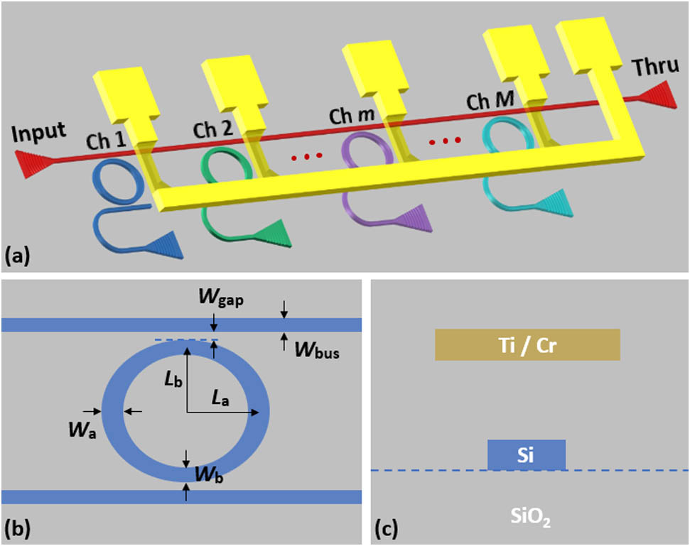
Figure 1(a) shows the schematic configuration of the proposed reconfigurable multichannel amplitude equalizer with wavelength-channels (). Each MRR serves as a key element in the system by utilizing its inherent resonance characteristics. The resonance peaks of the MRRs are tuned thermally with the metal microheaters located on the top to realize the optical amplitude equalization for the given wavelengths. Here the microheater covers a portion of the microring, so that it helps to relax the precision requirement of the applied voltage for achieving high-precision wavelength alignment (even though the thermal-tuning efficiency of the microheaters degrades in some degree). As shown in Fig. 1(a), all the MRRs share the same bus waveguide, and they are arranged in parallel to work with the corresponding wavelength-channels (). This is totally different from the previously proposed scheme of integrating multiplexers/demultiplexers with tuning elements for the channels. Here multiple channels of WDM signals are input and output through the single bus waveguide for the present architecture. The optical power of each wavelength-channel is modified by appropriately shifting the resonance wavelength of the corresponding MRR. The drop port of the MRR can act as a monitor for characterization. As an example, in this paper the channel spacing is set to 200 GHz (), which is achieved by appropriately controlling the MRR radii in the design. Meanwhile, some slight thermal tuning is usually required to compensate the random wavelength-shifting due to the fabrication deviation and realize the desired wavelength alignment.
Figure 1.(a) Schematic configuration of the proposed amplitude equalizer based on MRRs. (b) Top view of an MRR. (c) Cross section of the thermal-tuning region in the MRR.
Figure 1(b) shows the schematic structure of the present MRR based on an elliptical microring. Here both the radius and the core width of the elliptical microring waveguide are varied adiabatically, as demonstrated in our previous work [38,39]. Here the elliptical microring is designed with a relatively large bending radius and a narrow core width in the coupling region, so that it is possible to achieve sufficient coupling between the microring and the access waveguide. On the other hand, the broadened waveguides with small bending radii are used in the noncoupling region, which helps reduce the cavity length of the microring and thus increase the FSR as desired for covering all the wavelength-channels. The broadened waveguide also helps reduce the transmission loss in a sharp bend. In this case, the waveguide width needs to be chosen carefully to suppress the undesired higher-order mode excitation. Figure 1(c) shows the cross-sectional view of the thermal-tuning region for the elliptical microring. The Ti/Cr microheater is introduced to heat the microring waveguide and thermally tune the resonance peak to achieve optical amplitude equalization at the desired wavelengths.
Here we consider the silicon-on-insulator (SOI) platform with a 220-nm-thick silicon core layer and a 2-μm-thick buried silicon dioxide layer. The operation wavelength of the equalizer is aligned at the C-band, which is the mainstream wavelength-band for optical communications. The MRRs are designed to operate with the transverse electric (TE) polarization. In order to ensure sufficient coupling efficiency and low coupling loss in the coupling region, we choose the minor axis of the elliptical microring as μ, and the corresponding waveguide width is chosen as μ (which is the minimum in the elliptical microring). The width of the bus waveguide for the MRRs is set as μ. The gap width is chosen as μ to ensure high-quality filling of the upper cladding in the fabrication process. On the other hand, in order to reduce the transmission loss in the microring and obtain a large FSR, the major axis of the elliptical microring is set as μ, and the corresponding waveguide width is chosen as μ. With this design, there are no higher-order modes excited in the microrings. Accordingly, the curvature radii at the vertices of the major axis and the minor axis are given as and . Correspondingly, the minimal and maximal radii in the present design are 3.06 μm and 4.57 μm, respectively.
Figure 2(a) shows the calculated spectral responses at the drop and through ports of the designed elliptical microring. Here a full-vectorial three-dimensional finite-difference time-domain (3D-FDTD) method was used for the simulation. It can be seen from the figure that the resonance peak has an extinction ratio (ER) higher than 20 dB and an excess loss less than 1 dB while the 3-dB bandwidth is about 0.22 nm. The compact design of the MRR results in a large FSR of . For the real application, the transmission loss at the through port of the th MRR working for the th channel should be low enough at the wavelength of ( is the resonance wavelength of the th MRR), so that it is possible to achieve low excess loss in the initialized state, where no additional attenuation is expected ideally. Therefore, the coupling strength between the microring and the bus waveguide should be chosen appropriately to guarantee a moderate 3-dB bandwidth. The inset of Fig. 2(a) shows that the transmission at the through port for the wavelength (where in this example) is nearly lossless, which meets the real requirement. Figure 2(b) shows the FDTD-simulated light propagation in the designed elliptical microring when operating at the resonance wavelength near 1535 nm. As can be seen, the resonator exhibits a strong resonance and the signal at the resonance is switched from the bus waveguide to the drop port. There is some slight interference observed at the input port, which is due to the back-coupling in the coupling region and the back-scattering in the MRR [40]. Finally, in order to obtain the designed channel spacing of 200 GHz (), the lengths of the major and minor axes of the MRRs in the array have a slight increment of 6.4 nm.
Figure 2.(a) Calculated spectral responses of the designed elliptical microring simulated by the 3D-FDTD method. (b) Simulated light propagation in the MRR working at the resonance wavelength near 1535 nm.
The designed reconfigurable amplitude equalizer based on elliptical microrings was fabricated with the process of electron-beam lithography (EBL) and inductively coupled plasma reactive ion etching (ICP-RIE). After completion of waveguide patterning, a 1.5-μm-thick upper cladding was grown by plasma enhanced chemical vapor deposition (PECVD). Then, the microheater was formed with the electron-beam evaporation and lift off processes. Finally, a 0.2-μm-thick protection layer was grown to prevent oxidation, followed by the ultraviolet lithography process and removal of silica in the electrode-pad areas.
Figure 3(a) shows the picture of the fabricated eight-channel amplitude equalizer containing eight elliptical microring units arranged in parallel. Here eight channels of WDM optical signals are input and output through the single bus waveguide. The microheaters for the eight MRRs are connected to a common ground. Figure 3(b) shows the microscope image of the focused grating coupler for importing and exporting optical signals with TE polarization (with a coupling loss about 3–4 dB), and it is possible to improve the fiber-chip coupling efficiency of when using some special grating couplers or edge couplers [41,42]. More details for the MRR unit are shown by the enlarged microscope image in Fig. 3(c).
Figure 3.Microscope images of the fabricated amplitude equalizer based on adiabatic elliptical microrings. (a) Eight-channel amplitude equalizer containing eight elliptical microring units. (b) Enlarged view of the focused grating coupler. (c) Enlarged view of the elliptical microring unit.
A broadband amplified spontaneous emission (ASE) light source was used to characterize the fabricated chip through the grating couplers. An optical spectrum analyzer (OSA) was applied to read out the output spectrum. The measured spectral responses of the fabricated amplitude equalizer were normalized with respect to the transmission of a 500-nm-wide single-mode straight waveguide connected with grating couplers on the same chip. After the chip was mounted on a printed circuit board (PCB) and wire-bonded to connect the electrical pads [as shown in Fig. 3(a)], an external software-controlled multiple voltage source was used to control the microheaters simultaneously. For the measurement, the chip was placed on a temperature controller (at 25°C) to avoid the random wavelength-shifting caused by the ambient temperature variation.
In order to precisely control the resonance shift, the thermal-tuning characteristics of the microheater were investigated first. The voltage applied to the eighth channel was increased from 0 to 0.8 V with a step of 0.01 V after the eight wavelength-channels were already initialized to be uniformly spaced with a channel spacing of 200 GHz. The measured transmission spectra at the through port of the amplitude equalizer are shown in Fig. 4(a). Here, for the sake of clarity, the transmission spectra are shown for the voltage changes with an increment of 0.02 V. As can be seen, the resonance-wavelength shift for a voltage increase of 0.8 V is about 7.2 nm, which is several times larger than the channel spacing and sufficient to cover the tuning range required for the desired amplitude equalization. The ER and the 3-dB bandwidth almost remain unchanged when the resonance peak moves, indicating that the microring performance does not degrade during the tuning process. Figure 4(b) shows the measured resonance-wavelength shift as the power applied to the microheater increases. Here the chip was placed on the temperature controller set with different temperatures of 25°C, 35°C, 45°C, and 55°C, respectively. It can be seen that the resonance wavelength varies linearly with a tuning efficiency of as the heating power increases. According to this tuning efficiency, the heating power and the voltage applied to the microheaters can be estimated easily, facilitating the precise tuning of the resonance peaks to achieve the amplitude equalization as desired.
Figure 4.(a) Transmission spectra at the through port of the eighth channel of the eight-channel amplitude equalizer as the applied voltage is increased from 0 to 0.8 V with a step of 0.02 V for the initialized state with uniform channel spacing of 200 GHz for clarity. (b) Measured resonance-wavelength shift as the power applied to the microheater increases. Here the chip was placed on the temperature controller set with different temperatures of 25°C, 35°C, 45°C, and 55°C, respectively. (c) Measured transmittances at the through port for the eighth operating wavelength as the heating power increases.
Figure 4(c) shows the measured transmittances at the through port for the eighth operating wavelength as the heating power increases. As can be seen, the transmittance at the leftmost corresponds to the initialized state of the amplitude equalizer with precalibration, when the heating power is . In this state, light transmits to the through port with an excess loss about 0.5 dB at the operating wavelength (marked by the red star). When the applied electrical power increases to , the transmittance at the through port for the operating wavelength reaches the minimum, indicating that the attenuation has a high dynamic range of . Note that the relatively high heating power required for the eighth channel stems from the compensation for the random misalignment of the resonance peaks. It can be seen that the power change of the microheater corresponds to a specific optical power attenuation, which makes it possible to precisely control the output optical powers of all the channels, as shown in Fig. 4(c). Leveraging the determined relationship between the optical attenuation and the heating power, it is possible to develop an automated tuning system for the equalization of the chip working with many wavelength-channels.
With the careful characterization of the thermal tuning of the resonance peak for each MRR, the amplitude equalization becomes feasible by applying the required voltages/powers accordingly. Figures 5(a)–5(f) show the measured transmission spectra at the through port of the eight-channel amplitude equalizer when the eight microheaters are with different states, respectively. From Fig. 5(a), which shows the measured transmission spectrum when all eight microheaters are OFF, it can be seen that the resonance peaks of the eight MRRs are separated from each other and the channel spacing is roughly 200 GHz (). However, the channel spacing at the through port is inevitably nonuniform due to fabrication imperfections when no power is applied to the eight microheaters.
Figure 5.Measured transmission spectra at the through port of the eight-channel amplitude equalizer with different operating states. (a) Device performance after fabrication when all the eight microheaters are OFF. (b) Nonattenuation state with all the eight resonance wavelengths initialized to be deviated from the operating wavelengths by half of the channel spacing. Full-attenuation states when tuning some resonance peaks to be aligned with some of the operating wavelengths: (c) ; (d) , ; (e) , , ; (f) , , , .
In order to align with the wavelength-channels according to the International Telecommunication Union (ITU) standard, it is necessary to tune the resonance peaks of the MRRs carefully through the corresponding microheaters. Figure 5(b) shows the transmission spectrum when the eight resonance peaks are tuned to have uniform channel spacing of 200 GHz. Note that the resonance wavelengths () of all eight MRRs are preset initially to be deviated from the corresponding operating wavelengths () by half of the channel spacing (200 GHz in the present case), which is defined as the “nonattenuation” state for the amplitude equalizer. Here the power consumptions for the initialization of the resonance wavelengths of these eight MRRs are 2.42, 4.00, 2.38, 0.84, 0.07, 4.35, 3.89, and 4.96 mW, respectively. In this state, the signals of all the wavelength-channels launched from the bus waveguide directly output from the through port and very little optical power is dropped, indicating that there is little attenuation for the input signals. Meanwhile, the ERs of the through-port transmission spectrum for the eight MRRs can be up to 20 dB, which corresponds to the maximum of the dynamic range.
When the resonance peak of any MRR is red-shifted by 100 GHz from the nonattenuation state to align the resonance wavelength to be the same as the corresponding operating wavelength [marked by the red dotted line shown in Figs. 5(a)–5(f)], one realizes the “full-attenuation” state for the corresponding wavelength-channel. It can be seen that the output optical powers of the eight wavelength-channels can be tuned independently and thus be equalized possibly by controlling the heating powers of the microheaters. Figures 5(c)–5(f) demonstrate the measured transmission spectra at the through port when some of the eight channels are at the full-attenuation state [i.e., channels #1, #3, #5, and #7 in Fig. 5(f)]. The power consumptions for the five different operating states in Figs. 5(b)–5(f) are 22.9, 26.3, 30.5, 39.5, and 44.2 mW, respectively.
In addition, it is possible to tune the resonance peaks of adjacent wavelength-channels to be overlapped, which provides great potential for flexibly reconfiguring the amplitude equalization. Figures 6(a)–6(e) show the measured transmission spectra at the through port for the cases of overlapping the adjacent resonance peaks. With this flexible tunability, ERs can be improved greatly to further maximize the attenuation dynamic range. Here the results in Fig. 6(a)–6(e) are achieved by tuning the resonance peaks of channels #7 and #8 to operating wavelength [Fig. 6(a)]; the resonance peaks of channels #1 and #2 and channels #7 and #8 to operating wavelengths [Fig. 6(b)]; the resonance peaks of channels #1, #2, and #3, channels #7 and #8 to operating wavelengths [Fig. 6(c)]; the resonance peaks of channels #1, #2, #3, and #4, channels #7 and #8 to operating wavelengths [Fig. 6(d)]; and the resonance peaks of channels #1 and #2, channels #3, #4, and #5, channels #6, #7, and #8 to operating wavelengths , and [Fig. 6(e)]. In this way, the attenuation dynamic range is even up to 50 dB, as shown in Figs. 6(d) and 6(e). This is useful for some special applications where a high amplitude attenuation is required. Here the power consumptions in Figs. 6(a)–6(e) are 36.4, 53.8, 76.8, 117.7, and 144.9 mW, respectively.
Figure 6.Measured transmission spectra at the through port of the eight-channel amplitude equalizer when the resonance peaks of adjacent wavelength-channels are tuned to be overlapped with each other. Attenuation states when tuning some resonance peaks to be aligned with some of the operating wavelengths. (a) ; (b) , ; (c) , ; (d) , ; (e) , , and .
The present multichannel amplitude equalizer was then used to demonstrate the dynamic power equalization of multiple optical sources. Here eight laser sources with a tunable channel spacing of 50 GHz at the C-band were used for the multiple wavelength-channels and were combined by an AWG. The eight multiplexed channels with different optical powers [shown in Fig. 7(a)] were then injected as a multiwavelength source to the input port of the present amplitude equalizer. Figure 7(a) shows the measured transmission spectra of the amplitude equalizer with all channels initialized to be at the nonattenuation state. Note that the resonance wavelengths () of all eight MRRs are initially aligned to be deviated from the corresponding operating wavelengths () by half of the channel spacing. Figure 7(b) demonstrates the power equalization of the eight wavelength-channels by precisely controlling the heating powers for the corresponding MRRs, providing specific power attenuation for each channel to be equalized with power variation less than 0.5 dB. When all the channels operate with the full-attenuation state (i.e., ), all eight channels are attenuated by , as shown in Fig. 7(c). Furthermore, overlapping the resonance peaks of adjacent wavelength-channels enables very high attenuation of for the target channel, as shown in Fig. 7(d). In this experiment, the resonance peaks are tuned thermally so that , and . It can be seen that the power attenuations for channels #2 and #8 are about 37 dB and 49 dB, while the power attenuation for channel #5 is as high as 57 dB, verifying that the present multichannel amplitude equalizer can be reconfigured flexibly for achieving a very large dynamics range. As might be noticed, Fig. 7(d) shows that there are two peaks located at 1541.4/1543 nm, which is due to the sidelobes of the laser sources. Here the total power consumptions for the operations corresponding to Figs. 7(a)–7(d) are 22.6, 54.7, 68.7, and 145.8 mW, respectively. Note that the microheater used here only covers a portion of the microring, in which way the power consumption is relatively high while improved thermal-tuning precision can be achieved. When necessary, one can further reduce the power consumption by introducing deep-etching down to the silicon substrate with air trenches [29,31].
Figure 7.Measured results , , and at the through port of the eight-channel amplitude equalizer, where is the measured spectral response at the through port of the equalizer, is the measured transmission at the through port when eight channels of lasers are launched to the equalizer operating at the initialized state, and is the measured transmission at the through port when eight channels of lasers are launched to the equalizer operating to optimally attenuate the channels as desired. (a) Measured results at the nonattenuation state with all the eight resonance wavelengths initialized to be deviated from the operating wavelengths by half of the channel spacing. (b) Measured results when the eight channels are equalized to be with the same amplitude by appropriately tuning the resonance peaks. (c) Measured results when all the eight resonance wavelengths are tuned thermally to be aligned with the operating wavelengths. (d) Measured results when the resonance peaks are tuned thermally so that , , and .
Table 1 gives a summary between the proposed amplitude equalizer with MRRs and the previous configuration with the integration of AWGs/VOAs. As can be seen, the present amplitude equalizer has superior performance with low excess losses, low power consumption, and footprint compactness. Furthermore, the present structure can be scaled up very flexibly. Here, power equalization for eight channels is demonstrated and the number of the wavelength-channels can be definitely increased by maximizing the FSR and reducing the 3-dB bandwidth of the MRR to enable narrow channel spacing. The FSR can be extended by minimizing the cavity length (the bending radius) or introducing cascaded MRRs with the Vernier effect [43,44]. Currently a single MRR with an FSR as large as 93 nm has been reported previously [45] and cascaded MRRs have shown an FSR as large as 37 nm [38], which is sufficient for dense-wavelength-division-multiplexing (DWDM) systems with many channels.
Summary of the Reported Multichannel Amplitude Equalizers
Type
Channel Number
On-Chip Excess Loss (dB)
Power Consumption per Channel (mW)
Total Footprint ()
Footprint per Channel ()
[32]
16
2.2
(for 25 dB)
[33]
40
4.6
(for 20 dB)
[28]
(SOI)
4
6
(for 15 dB)
[23]
AWG () + p-i-n type Si waveguide (SOI)
16
13.5
(for 20 dB)
This work
MRR (SOI)
8
0.5
(for 20 dB)
4. CONCLUSION
In conclusion, we have proposed and demonstrated a reconfigurable multichannel optical amplitude equalizer based on cascaded elliptical microrings. The fabricated eight-channel amplitude equalizer on silicon has shown an average excess loss less than 0.5 dB for all the channels in the initialized state. Meanwhile, the measured dynamic range of attenuation is up to 20 dB and can be improved to reach 50 dB by overlapping the resonance peaks of multiple adjacent wavelength-channels, which greatly enhances the operation freedom of the amplitude equalizer. We have also shown that the fabricated device can implement dynamic power equalization of multiple WDM channels simultaneously. Note that optical amplitude equalization demonstrated here is realized by thermally tuning the resonance peaks of the MRRs, while it will be very attractive to utilize electro-optic effects for fast and energy-efficient equalization in the future. As a summary, the proposed architecture with excellent scalability and flexible tunability is of great significance for the development of WDM systems for optical interconnects [46–49], optical computing [4,5,50], as well as microwave photonics [9,48,51,52].