• Photonics Research
  • Vol. 10, Issue 11, 2460 (2022)
Atri Halder* and Jari Turunen
Author Affiliations
  • Institute of Photonics, University of Eastern Finland, FI-80101 Joensuu, Finland
  • show less
    DOI: 10.1364/PRJ.461314 Cite this Article Set citation alerts
    Atri Halder, Jari Turunen. Spectral coherence of white LEDs[J]. Photonics Research, 2022, 10(11): 2460 Copy Citation Text show less

    Abstract

    We address space–frequency domain coherence properties of broadband light-emitting diodes (white LEDs) and fields radiated by them. Inverse-source techniques are employed to determine the spectral degree of spatial coherence of an effective planar source representing a real LED, and coherent elementary fields associated with it. By fitting with experimental measurements, we formulate simple analytical coherence models that can be used as a basis for theoretical and experimental studies of the coherence of polychromatic stationary light in free space and in various optical systems. In particular, we find that radiation from white LEDs follows closely Wolf’s scaling law for spectral invariance [Phys. Rev. Lett.56, 1370 (1986)PRLTAO0031-900710.1103/PhysRevLett.56.1370] in the blue and the phosphor-generated parts of the spectrum separately, but not across the entire white-light spectrum.

    1. INTRODUCTION

    The progress in the development of white LEDs over the past quarter of a decade has revolutionized lighting technology, in particular, Refs. [1,2], but these compact and bright broadband sources have a lot to offer also in other fields of optical science and technology. The radiation from white LEDs is generally understood to have low spatial coherence across the spectrum and be more or less unpolarized. While this information may be sufficient for most solid-state lighting applications, more quantitative information is required in other applications of low-coherence light, such as holographic displays [3]. More generally, this is true for (LED-based) low-coherence imaging systems, where the image properties and resolution are well known to depend on the state of coherence of illumination [4]. It is therefore important to characterize in detail the spectral dependence of spatial coherence of these sources and of fields radiated by them in homogeneous media and in passage through optical systems. This is the main goal of the present paper; we address it by both theoretical and experimental means.

    Physically, a typical white LED consists of a primary blue LED and a volume of phosphorous material for downconversion of blue radiation into a wide band of frequencies that appears visually yellow. The light-emitting structure is enclosed within a transparent dome with a hemispherical or aspherical shape that allows some control over the directionality of radiation. In our model, we treat the white LED as an effective planar, quasihomogeneous, unpolarized source, whose coherence properties are determined from its radiant intensity distribution by an inverse-source approach [5] summarized in Sect. 5.3.3 of Ref. [6]. A variant of this inverse method is also applied to find an “elementary” fully coherent source that, by definition, produces the same distribution of radiant intensity as the white LED itself. This permits us to model the LED source by an incoherent superposition of laterally shifted replicas of the elementary source field [7,8]. Such elementary-field representations can significantly simplify the treatment of partially coherent beam shaping and imaging problems [9,10].

    Further, we consider secondary sources obtained by imaging our planar, effective, model source using optical systems with specified numerical apertures (NAs). The spatial scale of the complex degree of coherence of this secondary source can be controlled by the NA and the magnification of the imaging system. On the other hand, the intensity distribution of the secondary source can be controlled by spatial filtering (using, e.g., a spatial light modulator), and its frequency content can be controlled by spectral filtering. All this, put together, allows one to realize bright broadband sources with tunable spatial (and temporal) coherence properties.

    The model is applied to real white LEDs with either near-Lambertian or more directional distributions of radiant intensity. We introduce space–frequency-domain coherence models based on the inverse-source technique and fit the parameters to experimental measurements. The results are sufficiently accurate and simple to serve as a model for real white LEDs in both theoretical and experimental studies of a multitude of phenomena related to partially coherent beams. Special attention will be paid to the question of whether radiation from white LEDs follows Wolf’s scaling law on spectral invariance [11].

    2. THEORETICAL FRAMEWORK

    Assuming scalar theory of light throughout this paper for simplicity (c.f. Ref. [12] for an electromagnetic approach to LEDs), we begin by establishing the theoretical background required to develop the procedure for determination of the spectral coherence properties of quasihomogeneous sources such as white LEDs. We make use of the inverse-source technique [6] to determine the low-frequency (non-evanescent) part of the complex degree of spatial coherence at the plane of an effective (virtual) planar source from the radiant intensity distribution produced by the real source. Since we are dealing with broadband (instead of quasimonochromatic) sources, the frequency dependence of spatial coherence becomes significant and will be shown explicitly in all expressions.

    Referring to Fig. 1, the cross-spectral density (CSD) function [6] of any quasihomogeneous source at two transverse points ρ1 and ρ2 at frequency ω, W(ρ1,ρ2,ω), factors in average and difference spatial coordinates ρ¯=(ρ1+ρ2)/2 and Δρ=ρ2ρ1 as W(ρ¯,Δρ,ω)=S(ρ¯,ω)μ(Δρ,ω),where S(ρ¯,ω) is the spectral density, and μ(Δρ,ω) is the complex degree of spectral coherence at the source plane. The spectral angular cross-correlation function (ACF), defined as T(κ1,κ2,ω)=1(2π)4W(ρ1,ρ2,ω)×exp[i(κ1·ρ1κ2·ρ2)]d2ρ1d2ρ2,takes on the form T(κ¯,Δκ,ω)=1(2π)4W(ρ¯,Δρ,ω)×exp[i(Δκ·ρ¯+κ¯·Δρ)]d2ρ¯d2Δρif we introduce average and difference spatial-frequency coordinates κ¯=(κ1+κ2)/2, Δκ=κ2κ1. On inserting from Eq. (1) into Eq. (3), we find that the ACF of any quasihomogeneous source has a factored form [6]: T(κ¯,Δκ,ω)=S˜(κ¯,ω)μ˜(Δκ,ω),where we have defined Fourier transforms S˜(Δκ,ω)=1(2π)2S(ρ¯,ω)exp(iΔκ·ρ¯)d2ρ¯and μ˜(κ¯,ω)=1(2π)2μ(Δρ,ω)exp(iκ¯·Δρ)d2Δρof the source-plane spectral density and complex degree of spectral coherence, respectively.

    Geometry and notation relating to a quasihomogeneous planar source with an emitting area S far larger than the effective coherence area C, and far-field radiation from such a source. Here ρ1 and ρ2 represent two arbitrary points in the source plane. The unit vector s^=(s⊥,sz) refers to an arbitrary position r=rs^ at a distance r in the far zone.

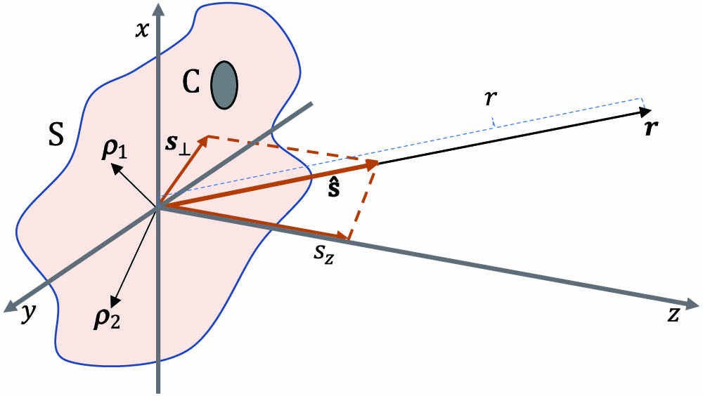
    Figure 1.Geometry and notation relating to a quasihomogeneous planar source with an emitting area S far larger than the effective coherence area C, and far-field radiation from such a source. Here ρ1 and ρ2 represent two arbitrary points in the source plane. The unit vector s^=(s,sz) refers to an arbitrary position r=rs^ at a distance r in the far zone.

    In general, the CSD at distance r in the far zone is related to the ACF by the formula [6] W()(rs^1,rs^2,ω)=(2πωrc)2sz1sz2T(ωcs1,ωcs2,ω),where s^j=(sj,szj), j=1,2 are unit position vectors as illustrated in Fig. 1, and sj are their transverse components. Using average and difference coordinates s¯=(s1+s2)/2 and Δs=s2s1, and Eq. (4), gives W()(rs^1,rs^2,ω)=(2πωrc)2sz1sz2S˜(ωcΔs,ω)μ˜(ωcs¯,ω).Hence the spectral density and the complex degree of spectral coherence in the far zone take the forms S()(rs^,ω)=(2πωrc)2sz2S˜(0,ω)μ˜(ωcΔs,ω)and μ()(rs^1,rs^2,ω)=S˜[(ω/c)Δs,ω]S˜(0,ω),respectively. In view of Eq. (5), the quantity S˜(0,ω)=1(2π)2S(ρ,ω)d2ρrepresents the source-integrated intensity at frequency ω.

    Our purpose is to model broadband light sources (white LEDs) on the basis of measurable quantities. To this end, we need full information on the source-plane CSD; with that available, we can readily model also the field in the far zone using Eqs. (8)–(10). The source-plane spectral density can be measured straightforwardly by (spectral) imaging, and this allows us to determine the complex degree of angular spectral coherence using Eq. (10). On the other hand, the spectral distribution of the radiant intensity J(s^,ω)=limrrS()(rs^,ω)=(2π)2sz2(ω/c)2S˜(0,ω)μ˜(ωcs,ω)is measurable by a goniometric setup involving a spectrum analyzer. This leads to knowledge on the source-plane complex degree of spectral coherence as shown below.

    By Fourier inversion of Eq. (6) and keeping in mind that only the low-frequency (non-evanescent) part of the radiation is observable in the far zone, we have μ(Δρ,ω)=|κ|<ω/cμ˜(κ,ω)exp(iκ·Δρ)d2κ.Setting κ=(ω/c)s and inserting from Eq. (12), we obtain μ(Δρ,ω)=1(2π)2S˜(0,ω)×LFJ(s^,ω)1s2exp(iωcs·Δρ)d2s,where LF means the low-frequency part of the field, |s|<1. Requiring that μ(0,ω)=1, we have the final general result: μ(Δρ,ω)=LF(1s2)1J(s^,ω)exp[i(ω/c)s·Δρ]d2sLF(1s2)1J(s^,ω)d2s.Assuming rotational symmetry and denoting s=|s|=sinθ, Δρ=|Δρ|, Eq. (15) takes the form μ(Δρ,ω)=01s(1s2)1J(s,ω)J0[(ω/c)Δρs]ds01s(1s2)1J(s,ω)ds,where J0(x) is the Bessel function of order zero. This is the inverse formula needed for the determination of the low-frequency part of the spectral degree of coherence at the source plane.

    3. ELEMENTARY-FIELD REPRESENTATION

    It is well known that the CSD of any Schell-model field at frequency ω can be represented as an incoherent superposition of spatially shifted fully coherent elementary fields (see Ref. [8] for a review). For quasihomogeneous sources defined in Eq. (1), the complex degree of coherence takes the form [7] μ(Δρ,ω)=1C2f(ρ¯ρΔρ/2,ω)×f(ρ¯ρ+Δρ/2,ω)d2ρ,where f(ρ,ω) represents the elementary field, and C2=|f(ρ,ω)|2d2ρ.The elementary field can be interpreted as a coherent field that produces the same distribution of radiant intensity as the entire partially coherent field does.

    Considering a single (fully coherent) elementary field f(ρ,ω), we may write the CSD at the source plane in the separable form W(ρ1,ρ2,ω)=f(ρ1,ω)f(ρ2,ω)and define the Fourier transform of f(ρ,ω) as f˜(κ,ω)=1(2π)2f(ρ,ω)exp(iκ·ρ)d2ρ.Then the radiant intensity reads as J(s^,ω)=(2π)2sz2(ω/c)2|f˜(ωcs,ω)|2.Clearly the radiant intensity specifies f˜ only up to phase. Choosing the phase as constant produces the most spatially compact (transform-limited) solution for the elementary field. In this case, f(ρ,ω)=12πLFJ1/2(s^,ω)(1s2)1/2exp(iωcs·ρ)d2s,and for rotationally symmetric radiant intensity distributions, we get f(ρ,ω)=f(0,ω)01s(1s2)1/2J1/2(s,ω)J0[(ω/c)ρs]ds01s(1s2)1/2J1/2(s,ω)ds,where f(0,ω) represents the axial spectral distribution in the elementary field.

    Let us consider, as an example, well-known cosine-power distributions for radiation from quasihomogeneous sources [6] by writing the radiant intensity in the form J(s^,ω)=J(ω)szp=J(ω)cospθ,where p0 is a real (but not necessarily integer) parameter. The value p=0 indicates an isotropically radiating source, p=1 a Lambertian source, p=2 an incoherent source, and larger powers describe sources with more directional radiation.

    To determine the spectral degree of spatial coherence and the functional form of the elementary field, we insert Eq. (24) into Eq. (16) and Eq. (23), respectively. The integrals involving the Bessel function can be evaluated with the formulas [13] 01x(1x2)μJ0(ax)dx=2μΓ(μ+1)Jμ+1(a)aμ+1and 01x(1x2)μdx=12(1+μ),where Γ is the gamma function, and Jμ is a Bessel function of order μ. The formula Eq. (25) holds for μ1. If we set μ=p/21, we get the well-known result [6] μ(Δρ,ω)=2p/2Γ(1+p2)Jp/2[(ω/c)Δρ][(ω/c)Δρ]p/2for the complex degree of coherence, which is valid when p0. If we set μ=q/41/2, we obtain the expression f(ρ,ω)=f(0,ω)2q/4+1/2Γ(32+q4)Jq/4+1/2[(ω/c)ρ][(ω/c)ρ]q/4+1/2for the elementary field, which is valid for p2.

    It is immediately seen that the forms of μ(Δρ,ω) as a function of Δρ and f(ρ,ω) as a function of ρ are the same if q=2(p1). Table 1 lists the explicit functional forms of the degree of coherence and the respective elementary field for some integer values of p and q. For brevity, we have written k=ω/c.

    Expressions for the Complex Degrees of Coherence and Elementary-Field Distributions for Selected Sources with Radiant Intensities Following the cospθ Law

    pμ(Δρ,ω)
    0J0(kΔρ)
    1sin(kΔρ)/kΔρ
    22J1(kΔρ)/kΔρ
    33[sin(kΔρ)kΔρcos(kΔρ)]/(kΔρ)3
    q=2(p1)f(ρ,ω)/f(0,ω)
    −2J0(kρ)
    0sin(kρ)/kρ
    22J1(kρ)/kρ
    43[sin(kρ)kρcos(kρ)]/(kρ)3

    Figure 2 illustrates the spatial distributions of μ(Δρ,ω) listed in Table 1. The distributions of f(ρ,ω)/f(0,ω) are identical if we set q=2(p1). The spatial scales of these functions get narrower as the value of p is reduced. If we look at the location of the first zero, the scale of the degree of coherence becomes sharper than that produced by an incoherent source when 0p<2. Similarly, the elementary field becomes sharper than the classical Airy form when 2q<2. However, this reduction in scale is achieved only at the expense of increased sidelobe intensity, in analogy with the improved spatial resolution achievable with coherent Bessel fields [14,15].

    Plots of the complex degree of coherence for sources with different values of p. Black: p=0. Red: p=1. Green: p=2. Blue: p=3.

    Figure 2.Plots of the complex degree of coherence for sources with different values of p. Black: p=0. Red: p=1. Green: p=2. Blue: p=3.

    4. COHERENCE OF SECONDARY SOURCES

    Imaging systems with specified NAs are frequently used to generate secondary light sources. In numerous instances, such a secondary source is assumed to be incoherent, though this is always an idealization. The model developed in this paper allows us to evaluate the spectral coherence properties of secondary white-light sources by means of the standard theory of image formation in an aplanatic system [16], illustrated in Fig. 3 in a scalar form.

    Aplanatic image formation in a system with object and image planes O and O′, principal planes P and P′, numerical apertures NA=sin Θ and NA′=sin Θ′, and focal lengths F and F′. Here S and S′ are the object and image-space reference spheres on which J(θ,ω) and J′(θ′,ω) are defined, respectively.

    Figure 3.Aplanatic image formation in a system with object and image planes O and O, principal planes P and P, numerical apertures NA=sinΘ and NA=sinΘ, and focal lengths F and F. Here S and S are the object and image-space reference spheres on which J(θ,ω) and J(θ,ω) are defined, respectively.

    To model the coherence of secondary sources, we employ the same process as in solving the inverse-source problem above. However, we limit the upper integration in Eqs. (16) and (23) only over the collection NA instead of the entire low-frequency part of the angular spectrum. Considering the field in the image space, we then have expressions μ(Δρ,ω)=0NAs(1s2)1J(s,ω)J0[(ω/c)Δρs]ds0NAs(1s2)1J(s,ω)dsfor the complex degree of spectral coherence and f(ρ,ω)f(0,ω)=0NAs(1s2)1/2J1/2(s,ω)J0[(ω/c)ρs]ds0NAs(1s2)1/2J1/2(s,ω)dsfor the elementary field associated with the secondary source. The function f(ρ,ω) defined in Eq. (30) can be considered as the elementary-field spread (EFS) function of the optical system under partially coherent illumination [10]. This concept may be viewed as an extension of the standard point-spread function (PSF) of an incoherent imaging system.

    According to the sine condition, satisfied by any aplanatic system, h=Fsinθ=Fsinθ in Fig. 3. Introducing the linear magnification M, we then have M=FF=sinθsinθ=NANA=sinΘsinΘ=ss=ΔρΔρ=ρρ.It follows from energy conservation that the radiant intensities J(θ,ω) on reference sphere S and J(θ,ω) on reference sphere S are related as J(θ,ω)cosθ=J(θ,ω)cosθor J(s,ω)=J(s,ω)[1s21(s/M)2]1/2=J(s,ω)P(s),where P(s) is a frequency-independent apodization factor. With these notations, Eqs. (29) and (30) take the forms μ(MΔρ,ω)=0NA/Ms[1(s/M)2]1P(s)J(s,ω)J0[(ω/c)Δρs]ds0NA/Ms[1(s/M)2]1P(s)J(s,ω)dsand f(Mρ,ω)f(0,ω)=0NA/Ms[1(s/M)2]1/2P(s)J1/2(s,ω)J0[(ω/c)ρs]ds0NA/Ms[1(s/M)2]1/2P(s)J1/2(s,ω)ds,respectively.

    Figure 4 illustrates the distributions of f(ρ,ω)/f(0,ω) in a unit-magnification (M=1) imaging system. Here we fix the value of q and plot the elementary-field response functions for different values of NAs for systems illuminated by Lambertian (p=1, q=0), isotropic (p=0, q=2), and more directional (p=4, q=6) primary sources. The distributions of μ(Δρ,ω) are of the same form when plotted as a function of Δρ. The thin dashed lines in Fig. 4 show the results for an incoherent primary source for comparison.

    Effect of the finite numerical aperture of the imaging system in the elementary-field spread function for (a) Lambertian primary sources with q=0, (b) isotropically radiating sources with q=−2, and (c) more directional sources with q=6. Black: NA=1. Red: NA=0.85. Green: NA=0.7. Blue: NA=0.5. Dashed black: incoherent primary source (q=2).

    Figure 4.Effect of the finite numerical aperture of the imaging system in the elementary-field spread function for (a) Lambertian primary sources with q=0, (b) isotropically radiating sources with q=2, and (c) more directional sources with q=6. Black: NA=1. Red: NA=0.85. Green: NA=0.7. Blue: NA=0.5. Dashed black: incoherent primary source (q=2).

    In general, the effect of reducing the NA leads to widening of the scales of both the effective degree of coherence and the effective elementary field. This effect is, for the degree of coherence, well known in the standard theory of incoherent imaging [4]. Because of the intimate relation between the CSD and the associated elementary field, expressed in Eq. (17), the scale of the latter follows the same trend. It is seen that the distributions of EFS for Lambertian and isotropically radiating primary sources are narrower than those for incoherent sources, and the same applies to the associated degrees of coherence. However, this narrowing happens at the expense of increased sidelobe level. The effect becomes less significant when the NA is reduced, since then only a central region of the low-frequency part of the field is collected and contributes to the EFS function.

    5. RELATION TO WOLF’S SCALING LAW

    The normalized spectrum s()(rs^,ω) of the field in the far zone is defined by dividing the spectrum by its frequency integral. In view of Eq. (8), we therefore have s()(rs^,ω)=S()(rs^,ω)0S()(rs^,ω)dω=J(θ,ω)0J(θ,ω)dω.The normalized spectrum generally varies as a function of direction θ, but if the radiant intensity is of the separable form J(θ,ω)=J(θ)J(ω), we immediately see that s()(rs^,ω)=J(ω)0J(ω)dω,i.e., the normalized spectrum is independent of the propagation direction. The field is then said to be spectrally invariant in the far zone [11]. It now follows from Eq. (16) that the source-plane complex degree of coherence has the form μ(Δρ,ω)=H(ωcΔρ)=01s(1s2)1J(s)J0[(ω/c)Δρs]ds01s(1s2)1J(s)ds.This specific form of the function H is known as Wolf’s scaling law for spectrally invariant fields [11]. The normalized source-integrated spectrum at the source plane, s(ω)=S˜(0,ω)0S˜(0,ω)dω,with S˜(0,ω) defined in Eq. (11), satisfies s(ω)=s()(ω).

    Considering the elementary-field representation of primary sources and assuming a separable distribution of the radiant intensity, it follows from Eq. (23) that f(ρ,ω)f(0,ω)=F(ωcρ)=01s(1s2)1/2J1/2(s)J0[(ω/c)ρs]ds01s(1s2)1/2J1/2(s)ds,i.e., the function F is of a specific form that ensures the directional invariance of the radiant intensity. Corresponding results can also be obtained for secondary sources produced by imaging systems, showing that they also obey Wolf’s scaling law and thereby produce directionally invariant far-zone distributions if the radiant intensity is separable.

    6. COHERENCE OF WHITE LEDS

    Our experimental setup for measuring the spectral coherence properties of real white LEDs is shown in Fig. 5. To measure these properties over the full low-frequency region, we place the LED on a rotation stage and any detector D on a fixed spatial position. Three types of measurements have been performed. In measurements of the radiant intensity, D is a fiber spectrometer (AvaSpec-2048), with spectral resolution 0.56 nm, and the rotation stage is scanned over the range 0°<θ<90° with 5° intervals for the “Lambertian” LED and 0°<θ<51° with 3° intervals for the “directional” LED.In measurements of the spectral distributions of source-plane intensity, D is an imaging system in which we use narrowband (FWHM of 2–4 nm) spectral filters centered at wavelengths 488, 515, 532, and 633 nm.In measurements of the far-zone degree of spectral coherence, we employ a 1D wavefront-folding interferometer [17] with a grating (Thorlabs GR25-0310, having 300 lines/mm), a cylindrical lens of focal length 10 cm, and a camera (CMOS, Thorlabs DCC1545M-GL); see Fig. 6.

    Goniometric experimental setup used for the measurements, with the white LED mounted on a rotation stage R, and a detector D in a fixed position. Polar plots of Lambertian (p=1, black), incoherent (p=2, red), and more directional (p=6, blue) distributions of J(θ,ω) are also shown.

    Figure 5.Goniometric experimental setup used for the measurements, with the white LED mounted on a rotation stage R, and a detector D in a fixed position. Polar plots of Lambertian (p=1, black), incoherent (p=2, red), and more directional (p=6, blue) distributions of J(θ,ω) are also shown.

    Schematic of the detector setup used for far-field spectral coherence measurement. The solid red line shows the principle ray. BS, beam splitter; LM, corner mirror; G, grating of 300 lines/mm; L, cylindrical lens of focal length f; CAM, CMOS camera. The lens collects the +1st diffraction order.

    Figure 6.Schematic of the detector setup used for far-field spectral coherence measurement. The solid red line shows the principle ray. BS, beam splitter; LM, corner mirror; G, grating of 300 lines/mm; L, cylindrical lens of focal length f; CAM, CMOS camera. The lens collects the +1st diffraction order.

    Moderate spectral (and angular) resolution is needed in radiant-intensity measurements. However, the source-plane intensity distribution depends only weakly on wavelength, which justifies the use of bandpass filters in these measurements. In the setup of Fig. 6, spectral interference fringes formed at CAM in the direction perpendicular to the plane of the paper allow the measurement of μ()(rs^1,rs^2,ω) in Eq. (10) over a range Δθ[0.2°,+0.2°] around any chosen angle θ. This is sufficient since μ() is a narrow function of Δs, which is the same for all s¯. In the experiments, we therefore chose θ=0°.

    We consider in detail the results for two representative white LEDs. The first (ProLight Opto, PM2E-3LWS-SD cool white) is nearly Lambertian because the dome that encloses the active LED structure is more or less hemispherical. We will refer this as a “Lambertian” LED. The second LED (SLOAN, L5-W602-PQBC, cool white) has a collimating dome, and it therefore has a more directional radiant intensity pattern.

    Figures 7(a) and 7(b) show the directly measured far-field spectra as a function of the diffraction angle for the Lambertian and directional LEDs in arbitrary units, respectively. Both spectra consist of a blue peak due to the primary LED and a wider yellow peak due to fluorescence, which are at approximately the same positions on the wavelength scale for both LEDs. Looking along the θ axis, the frequency-integrated distributions of the radiant intensity are shown on the right in Figs. 7(a) and 7(b) as black lines, along with the closest cospθ fits shown in red. The Lambertian LED indeed follows Lambert’s law quite well up to angles close to 80°, the failure beyond that being due to packaging issues. The radiant intensity of the directional LED can be approximated with p=56 in Eq. (24).

    Measured radiant intensities as a function of wavelength and θ for (a) Lambertian and (b) directional LEDs (in the latter case, the spectral data were averaged over an interval Δλ=5.3 nm to reduce experimental noise). Moreover, for theoretical comparison, the respective frequency-integrated radiant intensities are plotted as a function of θ on the right side of (a) and (b) in red [using Eq. (24)] and in black (measured). The normalized spectra are shown in (c) and (d), and the numerically calculated complex degree of coherence at the source plane in (e) and (f).

    Figure 7.Measured radiant intensities as a function of wavelength and θ for (a) Lambertian and (b) directional LEDs (in the latter case, the spectral data were averaged over an interval Δλ=5.3  nm to reduce experimental noise). Moreover, for theoretical comparison, the respective frequency-integrated radiant intensities are plotted as a function of θ on the right side of (a) and (b) in red [using Eq. (24)] and in black (measured). The normalized spectra are shown in (c) and (d), and the numerically calculated complex degree of coherence at the source plane in (e) and (f).

    Figures 7(c) and 7(d) show the normalized spectra s()(rs^,ω), calculated from the directly measured spectra using Eq. (36), for several discrete values of θ. For the radiation to be spectrally invariant in the far zone, these should be the same; however, they are not for either the Lambertian or directional LED. The effect is particularly clear for the Lambertian LED: the contribution of the blue part reduces relative to the yellow part as θ increases. In the directional LED, the trend is the same but less obvious, not only because of the higher directionality, but most likely also because of chromatic effects in the dome.

    With all this being said, it is interesting to consider the case of low- or high-pass filtering of the spectrum. If we filter out the blue part at ω>3.73.8  rad/fs, we still have the yellow part left, which has a sufficient bandwidth for representing truly polychromatic sources in studies of most phenomena related to partially coherent polychromatic fields. As will be discussed in more detail below, this filtered spectrum is essentially direction invariant. The same is true if we filter out the yellow part. It can therefore be concluded that the two filtered contributions are individually spectrally invariant but their superposition is not.

    Finally, Figs. 7(e) and 7(f) show the source-plane distributions of the absolute values of the complex degree of coherence μ(Δρ,ω), determined numerically from the measured radiant intensities using Eq. (16). The transverse (Δρ) scales are chosen the same for both the Lambertian and directional LEDs to emphasize how much the effective spatial coherence area of the source depends on the directionality. On the other hand, the horizontal scale shows its frequency dependence across the visible spectrum, which is far from negligible.

    Measured source-plane distributions of the spectral density across the Lambertian LED through different narrowband filters are shown in the top row of Fig. 8. These measurements were done by adjusting the imaging system to produce the most compact image obtainable through the aberrated dome; hence, the results should be considered as images of a virtual planar source. Although the true emitting area of the blue primary LED is probably square shaped, we see blurring due to the 3D structure of the phosphor region and aberrations of the dome. For the directional LED, the results are qualitatively similar (though even more blurred), but the effective source size is larger due to the collimation effect of the dome. As expected, the results show only weak frequency dependence. However, the effective size of the virtual source nevertheless increases with the wavelength.

    Top row (a), (c), (e), (g): measured source-plane intensity distributions through spectral filters with central transmission wavelengths at 488, 515, 532, and 633 nm, respectively. Second row (b), (d), (f), (h): numerically calculated absolute values of the complex degree of angular spectral coherence. Third row (i)–(l): cross sections of measured interference patterns (blue) and their envelopes (red) in the far field. Bottom row: comparison of numerically calculated (m) and measured (n) angular spectral coherence.

    Figure 8.Top row (a), (c), (e), (g): measured source-plane intensity distributions through spectral filters with central transmission wavelengths at 488, 515, 532, and 633 nm, respectively. Second row (b), (d), (f), (h): numerically calculated absolute values of the complex degree of angular spectral coherence. Third row (i)–(l): cross sections of measured interference patterns (blue) and their envelopes (red) in the far field. Bottom row: comparison of numerically calculated (m) and measured (n) angular spectral coherence.

    The second row in Fig. 8 shows the absolute values of the far-field complex degree of spectral coherence μ()(rs^1,rs^2,ω) calculated from Eq. (10). These results show very little wavelength dependence and almost no sidelobes. To explain the results, we consider a “bare” LED with no dome and a square emitting area of size L×L. In view of Eq. (10), we would then have μ()(rs^1,rs^2,ω)=sin[(ω/c)LΔsx/2](ω/c)LΔsx/2sin[(ω/c)LΔsy/2](ω/c)LΔsy/2,indicating a linear frequency dependence of the scale of the far-zone coherence. However, according to the results in the top row of Fig. 8, the effective value of L decreases with ω, thus more or less making the final result frequency independent. While Eq. (41) also predicts strong sidelobes, the blurring of the source-place profiles reduces them significantly.

    The final two rows of Fig. 8 illustrate the results more quantitatively, by means of cross sections. The third row shows the (normalized) interference patterns recorded with the wavefront-folding interferometer in Fig. 6, and their envelopes. Indeed, the wavelength dependence of these results is weak. In Figs. 8(m) and 8(n), we plot collectively the cross-sectional profiles μ()(rsx1,rsx2,ω) as functions of Δθ: in Fig. 8(m) calculated from the measured profiles in the top row, and in Fig. 8(n) the directly measured far-zone results. Also these results demonstrate only weak wavelength dependence and sidelobes. The transverse widths of the profiles in Figs. 8(m) and 8(n) are in decent agreement, given that the calculated profiles in Fig. 8(m) depend to some degree on which image plane of the virtual source we choose.

    7. ANALYTICAL COHERENCE MODELS

    We proceed to develop analytical models for the spectral distribution of spatial coherence properties of white LEDs, based on measurements of the type described in the previous section. In view of Figs. 7(c) and 7(d), we have two distinct spectral peaks in the normalized far-field spectra, which suggests that the spectral model should be expressed as a sum of blue (B) and yellow (Y) contributions. On the other hand, in view of Figs. 7(a) and 7(b), we see that the angular distribution of J(θ,ω) can be well approximated by the model in Eq. (24) at least if we choose the power p separately for B and Y contributions. Based on these observations, we consider models of the type J(s,ω)=SB(ω)H(s,ωB)+SY(ω)H(s,ωY),where SB(ω) and SY(ω) are the spectral distributions of the B and Y parts, whereas H(s,ωB) and H(s,ωY) are the angular distributions at the center positions of the B and Y contributions.

    Motivated by the approach in Ref. [6], we express the functions H(s,ωB) and H(s,ωY) as H(s,ωB)=H(0,ωB)cosmθ=CB(1s2)m/2,H(s,ωY)=H(0,ωY)cosnθ=CY(1s2)n/2,where CB=H(0,ωB), CY=H(0,ωY), and m and n are real-valued fitting constants. Using Eq. (16), we can write the source-plane complex degree of coherence given by this model in the form μ(Δρ,ω)=m1CBSB(ω)LB(Δρ,ω)+n1CYSY(ω)LY(Δρ,ω)m1CBSB(ω)+n1CYSY(ω),where LB(Δρ,ω)=2m/2Γ(1+m2)Jm/2[(ω/c)Δρ][(ω/c)Δρ]m/2,LY(Δρ,ω)=2n/2Γ(1+n2)Jn/2[(ω/c)Δρ][(ω/c)Δρ]n/2.On the other hand, using Eq. (23), we have the elementary-field model f(ρ,ω)f(0,ω)=(1+m/2)1CBSB(ω)KB(ρ,ω)+(1+n/2)1CYSY(ω)KY(ρ,ω)(1+m/2)1CBSB(ω)+(1+n/2)1CYSY(ω),with LB(ρ,ω)=2m/4+1/2Γ(32+m4)Jm/4+1/2[(ω/c)ρ][(ω/c)ρ]m/4+1/2,LY(ρ,ω)=2n/4+1/2Γ(32+n4)Jn/4+1/2[(ω/c)ρ][(ω/c)ρ]n/4+1/2.

    It may be worth stressing at this point that the model given by Eq. (44) no longer assumes the separability of the radiant intensity in angular and spectral contributions in the sense of Eq. (24). It now remains to find analytical expressions for the spectral contributions SB(ω) and SB(ω) to complete the model. Among numerous possible options, we consider those with the simplest analytical forms that yet reflect the main physical properties of the spectrum. In particular, we consider two cases: Sj(ω)=exp[2Ωj2(ωωj)2]and Sj(ω)=exp[2Ωj2(ωω0ωsωj)2],where j=B,Y. This approach is realistic because it is evident from Figs. 7(c) and 7(d) that the spectrum has two Gaussian-type distributions centered at two frequencies. In the latter model, ω0=0ωJ(0,ω)dω0J(0,ω)dωis the mean frequency of the measured axial radiant intensity, and ωs is a scaling parameter. While the model in Eq. (51) is mathematically simpler, the one in Eqs. (52) and (53) gives a better fit with the aid of the extra parameter ωs.

    The model parameters obtained for the angular distributions of the radiant intensity, given by H(θ,ωB) and H(θ,ωY), by least-squares fitting to the experimental results are listed in Table 2 for both the Lambertian and directional LEDs. In the case of the Lambertian LED, the Y part of the radiant intensity is sub-Lambertian, whereas the B part is super-Lambertian (close to the case of an incoherent planar source). This is also qualitatively evident from Fig. 7, as already mentioned. For the directional LED, m and n are closer to each other, but still clearly different.

    Model Parameters for the Angular Distribution of Radiant Intensity of the Lambertian and Directional LEDs

    Model [Eq. (51)]CBCYmn
    Lambertian1.651.201.970.77
    Directional1.450.7749.957.1
    Model [Eq. (52)]CBCYmn
    Lambertian1.461.171.440.94
    Directional1.470.6749.559.5

    The parameters obtained by least-squares fitting for J(0,ω) using both models are given in Table 3 for the Lambertian and directional LEDs. The standard deviations of the two models Eqs. (51) and (52) are 0.339 and 0.089 for the Lambertian source, and 0.302 and 0.181 for the directional source, respectively. Hence we may conclude that the model in Eq. (52) is indeed superior, in particular for the Lambertian LED.

    Model Parameters for the Spectral Distribution of Lambertian and Directional LEDsa

    Model [Eq. (51)]ωBΩBωYΩY
    Lambertian4.170.213.370.23
    Directional4.170.143.350.21
    Model [Eq. (52)]LambertianDirectional
    ωB0.230.23
    ΩB0.0780.069
    ωY−0.15−0.16
    ΩY0.180.15
    ω03.683.68
    ωs2.072.07

    All angular frequencies are in units rad/fs.

    Figure 9 shows a quantitative comparison of certain cross sections of experimentally measured radiant intensities and those given by the analytic models. In the top row, we illustrate the angular distributions of radiant intensity, and in the bottom row, the axial spectral distributions. The axial spectra are indeed represented well, especially by Eq. (52). The angular distributions match well for the Lambertian LED, and also for the directional LED in the yellow region. In the blue region, there is some mismatch, indicating that a single cosine power does not represent the radiant intensity accurately. The match could be improved by using a second cosine term as in Eq. (5-3-54) of Ref. [6].

    Top row: distributions of J(s,ωB) and J(s,ωY) for (a) Lambertian and (b) directional LEDs. Solid lines: measured. Dotted lines: model [Eq. (51)]. Dashed lines: model [Eq. (52)]. Blue: J(s,ωB). Red: J(s,ωY). Bottom row: distributions of J(0,ω) for (c) Lambertian and (d) directional LEDs. Black: measured. Blue: model [Eq. (51)]. Red: model [Eq. (52)].

    Figure 9.Top row: distributions of J(s,ωB) and J(s,ωY) for (a) Lambertian and (b) directional LEDs. Solid lines: measured. Dotted lines: model [Eq. (51)]. Dashed lines: model [Eq. (52)]. Blue: J(s,ωB). Red: J(s,ωY). Bottom row: distributions of J(0,ω) for (c) Lambertian and (d) directional LEDs. Black: measured. Blue: model [Eq. (51)]. Red: model [Eq. (52)].

    Finally, in Fig. 10, we present a comparison between the numerically calculated distribution of the source-plane complex degree of coherence, and the same calculated using Eq. (52), for the Lambertian LED. The numerically calculated absolute value and phase of the complex degree of coherence are shown in (a) and (b), and the model results given by Eq. (52) are illustrated in (c) and (d). We find that the prediction of the spectral degree of spatial coherence by the model is excellent. Moreover, the width of spatial coherence at the source plane decreases as the optical angular frequency increases except around ω3.83.9  rad/fs. In this frequency range, where the B and Y contributions of the model overlap, the width of the coherence function is nearly constant. This behavior is also seen in Fig. 7(c). The spectral fields on either side of this band individually follow Wolf’s scaling law to a good accuracy.

    Comparison between the numerically calculated distribution of the source-plane complex degree of coherence and from analytical model [Eq. (52)] for Lambertian LED. (a), (c) Absolute value. (b), (d) Phase. Calculated using Eq. (42).

    Figure 10.Comparison between the numerically calculated distribution of the source-plane complex degree of coherence and from analytical model [Eq. (52)] for Lambertian LED. (a), (c) Absolute value. (b), (d) Phase. Calculated using Eq. (42).

    8. DISCUSSION AND CONCLUSION

    Most of the work on spatially partially coherent fields, and on radiation that they emit, has over the past decades been mainly concentrated on quasimonochromatic sources and fields. While real sources of thermal or quasi-thermal light were of primary concern in the past, the advent of lasers changed the situation rather dramatically: it was no longer necessary to worry about the low brightness of previously available sources. Moreover, partial spatial coherence could be introduced artificially, e.g., by passing a single-mode laser beam through a rotating diffuser. With the advent of bright LEDs, we are now again in a new situation, having a class of bright sources available that are inherently partially spatially coherent and, moreover, an integral part of present-day life. However, these sources are broadband, not quasimonochromatic.

    In our opinion, white LEDs should not be considered merely as lighting devices but be taken under consideration as light sources in near-future (theoretical as well as experimental) scientific studies on coherence properties of light. Thorough understanding of the spatial coherence of white LEDs becomes vital at this stage. In this paper, we have taken some steps in this direction by presenting simple analytical models for their spectral coherence. Our formulation could be readily extended in several ways, such as increasing the number of cosine terms in Eq. (42) in analogy with Eq. (5-3-54) of Ref. [6]. One could also introduce better fits into the spectral distributions of the blue and yellow parts, for instance, by replacing the Gaussian profile assumed here with more sophisticated asymmetric profiles or adding extra Gaussian profiles centered at different frequencies and then fitting them in experimental results. However, the spectral model in Eq. (52) is sufficient for most purposes.

    To conclude, we started from theoretical considerations based on the inverse-source problems in partially coherent optics, taking the field to have a finite bandwidth instead of being quasimonochromatic. With the aid of measurements of real white LEDs, we developed models that are sufficiently simple to be used as a starting point of theoretical or experimental analysis of many phenomena or systems related to partially coherent light. Yet the models are sufficiently accurate to reflect the properties of real white LEDs. One of our key findings is that the LED with a near-Lambertian frequency-integrated radiant intensity has a super-Lambertian (m>1) blue part and a sub-Lambertian (n<1) yellow part of the spectrum. Hence, these two parts follow Wolf’s scaling law [11] separately, while the entire LED radiation does not.

    Finally, the identification of the sub-Lambertian radiation, which in our opinion originates from the volume nature of the fluorescence radiation from the true 3D physical source, could benefit microscopy. The resolution in microscopy is limited by the coherence area of the illumination [4], which is below that of the conventional limit (for critical and Köhler illumination) already for the Lambertian source. The reduction is enhanced further for sub-Lambertian sources, though only at the expense of increased sidelobe level.

    References

    [1] J. Cho, J. H. Park, J. K. Kim, E. F. Schubert. White light-emitting diodes: history, progress, and future. Laser Photon. Rev., 11, 1600147(2017).

    [2] C. Weisbuch. Review: on the search for efficient solid state light emitters: past, present, future. ECS J. Solid State Sci. Technol., 9, 016022(2020).

    [3] Y. Deng, D. Chu. Coherence properties of different light sources and their effect on the image sharpness and speckle of holographic displays. Sci. Rep., 7, 5893(2017).

    [4] M. Born, E. Wolf. Principles of Optics(1999).

    [5] H. P. Baltes, J. Geist, A. Walther. Radiometry and coherence. Inverse Source Problems, 119-154(1978).

    [6] L. Mandel, E. Wolf. Coherence and Quantum Optics(1995).

    [7] P. Vahimaa, J. Turunen. Finite-elementary-source model for partially coherent radiation. Opt. Express, 14, 1376-1381(2006).

    [8] J. Turunen. Elementary-field representations in partially coherent optics. J. Mod. Opt., 58, 509-527(2011).

    [9] M. Singh, J. Tervo, J. Turunen. Elementary-field analysis of partially coherent beam shaping. J. Opt. Soc. Am. A, 30, 2611-2617(2013).

    [10] M. Singh, H. Lajunen, J. Tervo, J. Turunen. Imaging with partially coherent light: elementary-field approach. Opt. Express, 23, 28132-28140(2015).

    [11] E. Wolf. Invariance of the spectrum of light on propagation. Phys. Rev. Lett., 56, 1370-1372(1986).

    [12] J. Tervo, J. Turunen, P. Vahimaa, F. Wyrowski. Shifted-elementary-mode representation for partially coherent vectorial fields. J. Opt. Soc. Am. A, 27, 2004-2014(2010).

    [13] I. S. Gradshteyn, I. M. Ryshik. Table of Integrals, Series, and Products, 687(2014).

    [14] J. Durnin, J. J. Miceli, J. H. Eberly. Diffraction-free beams. Phys. Rev. Lett., 58, 1499-1501(1987).

    [15] J. Turunen, A. T. Friberg. Propagation-invariant optical fields. Progress in Optics, 54, 1-88(2009).

    [16] L. Novotny, B. Hecht. Principles of Nano-Optics(2012).

    [17] D. Das, A. Halder, H. Partanen, M. Koivurova, J. Turunen. Propagation of Bessel-correlated specular and antispecular beams. Opt. Express, 30, 5709-5721(2022).

    Atri Halder, Jari Turunen. Spectral coherence of white LEDs[J]. Photonics Research, 2022, 10(11): 2460
    Download Citation