• Opto-Electronic Advances
  • Vol. 1, Issue 7, 180003 (2018)
Ruishan Chen1, Jinghao Wang1, Xiaoqiang Zhang1、2, Junna Yao1, Hai Ming1, and Anting Wang1、*
Author Affiliations
  • 1Department of Optics and Optical Engineering, University of Science and Technology of China, Hefei 230026, China
  • 2Hefei General Machinery Research Institute, Hefei 230031, China
  • show less
    DOI: 10.29026/oea.2018.180003 Cite this Article
    Ruishan Chen, Jinghao Wang, Xiaoqiang Zhang, Junna Yao, Hai Ming, Anting Wang. Fiber-based mode converter for generating optical vortex beams[J]. Opto-Electronic Advances, 2018, 1(7): 180003 Copy Citation Text show less
    Effective indices of different modes in the SMF (LP01 mode) and MMF (LP/1 modes) at a wavelength of 1550 nm.The black curve shows the effective index of the fundamental mode in the SMF as a function of the core radius. The horizontal lines show the effective indices of the LP/1 modes in the MMF32.
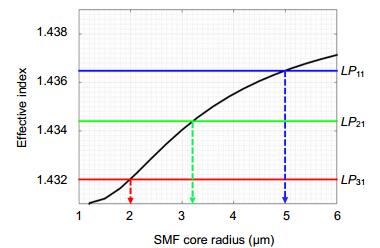
    Fig. 1. Effective indices of different modes in the SMF (LP01 mode) and MMF (LP/1 modes) at a wavelength of 1550 nm.The black curve shows the effective index of the fundamental mode in the SMF as a function of the core radius. The horizontal lines show the effective indices of the LP/1 modes in the MMF32.
    Normalized power conversion (a) from the LP01 mode to the \begin{document}$LP_{l1}^c $\end{document} mode in MSC1, (b) from the LP01 mode to the \begin{document}$LP_{21}^c $\end{document} mode in MSC2, and (c) from the LP01 mode to the \begin{document}$LP_{31}^c $\end{document} mode in MSC3 between the SMF and MMF as a function of coupling length L.Insets: simulated intensity profiles of the LP01 and \begin{document}$LP_{/1}^c $\end{document} modes.
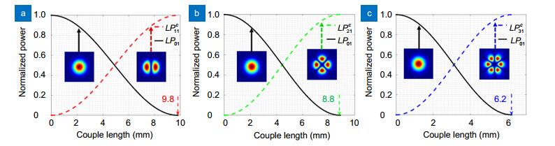
    Fig. 2. Normalized power conversion (a) from the LP01 mode to the \begin{document}$LP_{l1}^c $\end{document} mode in MSC1, (b) from the LP01 mode to the \begin{document}$LP_{21}^c $\end{document} mode in MSC2, and (c) from the LP01 mode to the \begin{document}$LP_{31}^c $\end{document} mode in MSC3 between the SMF and MMF as a function of coupling length L.Insets: simulated intensity profiles of the LP01 and \begin{document}$LP_{/1}^c $\end{document} modes.
    (a) Cross section and refractive-index distribution of the IECF.(b) Three-dimensional structure of the IECF.
    Fig. 3. (a) Cross section and refractive-index distribution of the IECF. (b) Three-dimensional structure of the IECF.
    Evolution diagrams of intensity and phase from the LP01 mode to the \begin{document}$LP_{11}^c $\end{document}, \begin{document}$LP_{21}^c $\end{document}, and \begin{document}$LP_{31}^c $\end{document} modes by coupling in the designed MSCs and those from the \begin{document}$LP_{11}^c $\end{document}, \begin{document}$LP_{21}^c $\end{document}, and \begin{document}$LP_{21}^c $\end{document} modes to the OAM±11, OAM±21, and OAM±31 modes after passing through the designed IECFs with different splicing angles of 45°, 22.5°, and 15°34.
    Fig. 4. Evolution diagrams of intensity and phase from the LP01 mode to the \begin{document}$LP_{11}^c $\end{document}, \begin{document}$LP_{21}^c $\end{document}, and \begin{document}$LP_{31}^c $\end{document} modes by coupling in the designed MSCs and those from the \begin{document}$LP_{11}^c $\end{document}, \begin{document}$LP_{21}^c $\end{document}, and \begin{document}$LP_{21}^c $\end{document} modes to the OAM±11, OAM±21, and OAM±31 modes after passing through the designed IECFs with different splicing angles of 45°, 22.5°, and 15°34.
    Normalized power evolution between the \begin{document}$LP_{l1}^c $\end{document} modes and \begin{document}$LP_{l1}^s $\end{document} modes along the propagation length of IECFs. The intersection points of each pair of curves are the corresponding positions of generation of OAM±l1 modes.
    Fig. 5. Normalized power evolution between the \begin{document}$LP_{l1}^c $\end{document} modes and \begin{document}$LP_{l1}^s $\end{document} modes along the propagation length of IECFs. The intersection points of each pair of curves are the corresponding positions of generation of OAM±l1 modes.
    Intensity, phase, interference, and local helicity distributions of the OAM mode with TCs of / = ±1 generated by MSC1 and IECF1 at different values of LIECF.
    Fig. 6. Intensity, phase, interference, and local helicity distributions of the OAM mode with TCs of / = ±1 generated by MSC1 and IECF1 at different values of LIECF.
    Purity of the first-order OAM mode generated by MSC1 cascaded with IECF1 at different values of LIECF.
    Fig. 7. Purity of the first-order OAM mode generated by MSC1 cascaded with IECF1 at different values of LIECF.
    ModeOAM11/OAM–11OAM21/OAM–21OAM31/OAM–31
    Δneff0.5×10–40.8×10–40.9×10–4
    Λ (mm)3119.417.22
    LIECF(mm)7.75/23.254.84/14.534.3/12.9
    Table 1. Structural parameters of IECFs for the generation of OAM modes
    Ruishan Chen, Jinghao Wang, Xiaoqiang Zhang, Junna Yao, Hai Ming, Anting Wang. Fiber-based mode converter for generating optical vortex beams[J]. Opto-Electronic Advances, 2018, 1(7): 180003
    Download Citation