Abstract
In this work, an all-fiber-based mode converter for generating orbital angular momentum (OAM) beams is proposed and numerically investigated. Its structure is constructed by cascading a mode selective coupler (MSC) and an inner elliptical cladding fiber (IECF). OAM modes refer to a combination of two orthogonal LPlm modes with a phase difference of ±π/2. By adjusting the parameters and controlling the splicing angle of MSC and IECF appropriately, higher-order OAM modes with topological charges of l = ±1, ±2, ±3 can be obtained with the injection of the fundamental mode LP01, resulting in a mode-conversion efficiency of almost 100%. This achievement may pave the way towards the realization of a compact, all-fiber, and high-efficiency device for increasing the transmission capacity and spectral efficiency in optical communication systems with OAM mode multiplexing. Introduction
Optical vortex beams (OVBs) possessing orbital angular momentum (OAM), i.e., OAM beams or OAM modes, with a helical phase wavefront indicated by the term exp(ilφ), where φ denotes the azimuth angle and l is an integer representing topological charges (TCs), have a phase singularity in the transverse phase center and a doughnut-shaped profile in the transverse intensity distribution1.
In recent decades, mode-division multiplexing has increasingly attracted attention as a method for increasing the transmission capacity and spectral efficiency of optical communication systems, with a special focus on multiplexing technology with OAM modes because of their infinite value of lћ per photon2-4. In addition, OAM beams have been developed for applications such as optical tweezers and atom manipulation5-7, microscopy8, as well as quantum information processing9.
A pivotal challenge is the generation of OAM beams, for which various methods have been developed. Free-space optical systems, such as spiral phase plates10, cylindrical lens converters11, and spatial light modulators (SLM)7-9, are relatively bulky or expensive. Hence, various fiber-based generation schemes have been investigated, such as acoustic-optic interaction12, mechanical stress-induced long-period grating13, 14, CO2 laser-inscribed long-period fiber grating15, offset splicing16 or pressure exertion17 in a single-ring fiber, and the superposition of two orthogonal LP11 modes with a micro phase difference, because of their superior robustness, low cost, compatibility, and high efficiency. In these previous papers, however, only OAM modes for l = ±1 have been achieved, which makes the development of high-capacity all-fiber communication systems based on OAM modes difficult. Therefore, it is highly desirable to generate high-order OAM (HO-OAM) modes. In our previous work, we theoretically studied the generation of first-order OAM modes18 and HO-OAM modes by using a helical fiber Bragg grating19. Moreover, Fang et al. simulated the flexible generation of HO-OAM modes by using helical long-period fiber gratings20-21. Furthermore, theoretical methods for generating HO-OAM modes were proposed by phase-matching coupling between different vector modes22-24. In addition, integrated photonics-based methods have been implemented for OAM multiplexing and generation, which realize relatively compact systems25-31.
In this letter, an all-fiber-based mode converter for the efficient generation of OAM modes with TCs of l = ±1, ±2, ±3 is proposed and simulated in detail. The mode converter is developed by combining a mode-selective coupler (MSC)32 and an inner elliptical cladding fiber (IECF). The MSC is used to generate LPlm modes, where l denotes the azimuthal index and m represents the radial index, which is assumed as 1, and the IECF can introduce a phase difference of ±π/2 between two degenerate orthogonal ($ LP_{l1}^{{\rm{even}}}$ and $ LP_{l1}^{{\rm{odd}}}$) modes after a certain propagation length. Consequently, the HO-OAM modes can be obtained with a high mode-conversion efficiency of close to 100%.
Mode-selective coupler
As a part of the proposed mode converter, the MSC is composed of a single-mode fiber (SMF) and a multimode fiber (MMF), which has been exploited to excite the high-order modes (HOM) LPl1 in MMF with high efficiency33. The MSC has been used to generate OAM beams34-35. If the refractive-index difference between the core and cladding is small enough to satisfy the weak guiding approximation, the linearly polarized (LP) mode can be applied in the fiber. Based on the coupled-mode theory, the principle of MSC is to reach the phase-matching condition between the fundamental mode LP01 in the SMF and HOM LPl1 in the MMF. If the effective indices or propagation constants are equal, the phase-matching condition can be satisfied and the power of the LP01 mode in the SMF can be completely transferred to the LPl1 mode in the MMF with fiber lengths that are odd multiples of the half beat coupling length. For an MSC composed of two dissimilar fibers, the output power in the MMF can be expressed as36
where Pc is the optical power of the HOM in the MMF; P0 is the optical power of the fundamental mode in the SMF; δ =(β1-β2)/2 is the phase-mismatch factor; β1 and β2 are the propagation constants of the normal mode in the SMF and MMF, which are both equal to 2π×neff/λ;
neff is the effective index; L is the coupling length; and κ is the coupling coefficient. The coupling coefficient can be expressed as32
where u1 and u2 are the core modal indices of the SMF and MMF, respectively; ω1 and ω2 are the cladding modal indices of the SMF and MMF, respectively; ν1 and ν2 are the normalized frequencies of the SMF and MMF, respectively;
l is the mode order in the azimuthal direction; k is the wave number; ρ1 and ρ2 are the core radii of the SMF and MMF, respectively; Δ2 is the relative index difference in the MMF; nco is the fiber-core refractive index; d is the distance between the SMF and MMF for MSCs; K is the modified Bessel function of the second kind; and α is the azimuthal angle shown in Fig. 1 in Ref.32.

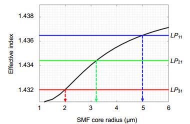
Figure 1.Effective indices of different modes in the SMF (LP01 mode) and MMF (LP/1 modes) at a wavelength of 1550 nm.The black curve shows the effective index of the fundamental mode in the SMF as a function of the core radius. The horizontal lines show the effective indices of the LP/1 modes in the MMF32.
It is assumed that the indices of the core and cladding are nco=1.4392 and ncl =1.431 for both the SMF and MMF, respectively; the distance between the SMF and MMF for MSCs is 18 μm; and the core radius of MMF is 9 μm. In order to completely transfer the power from the LP01 mode in the SMF to the LPl1 mode in the MMF, it is essential that the modes have the same neff or β. To achieve this, the SMF can be tapered to satisfy phase matching while the MMF has a constant diameter of 18 μm for easy cascading, as in Ref.37. In Fig. 1, the neff of the LP01 mode in the SMF as a function of the core radius (black curve) and those of the LPl1 modes in the MMF (horizontal color line) at a wavelength of λ =1550 nm are mapped. For realizing phase matching between the LP01 mode and the LP11, LP21, and LP31 modes, SMFs with different radii can be employed. Further, the radii of the SMFs of the MSCs (MSC1, MSC2, and MSC3) are equal to 5 μm, 3.21 μm, and 1.98 μm, respectively, as shown in Fig. 1.
Based on the given parameters, we simulate the performance of MSCs. From the analysis in Ref.32, the coupling coefficient between the LP01 mode and $ LP_{l1}^s$ mode (i.e., $LP_{l1}^s{\rm{ = }}{F_{l1}}(r){\rm{sin}}(l\varphi ) $, where Fl1(r) is the radial wave function for LPl1 modes) is zero when the two cores of the MSC are in the same horizontal plane. Thus, if the input mode is the fundamental mode LP01 in the SMF, only the $ LP_{l1}^c$ mode (i.e., $ LP_{l1}^c{\rm{ = }}{F_{l1}}(r){\rm{cos}}(l\varphi )$) can be selectively excited in the MMF. Figures 2(a)~2(c) show the normalized power conversion from the LP01 mode to the$LP_{{\rm{1}}1}^c $mode in MSC1, from the LP01 mode to the $ LP_{{\rm{2}}1}^c$ mode in MSC2, and from the LP01 mode to the $LP_{31}^c $ mode in MSC3, respectively. As the coupling length increases, the coupling power follows a sinusoidal oscillation. The coupling length L can be designed specifically to realize a maximum coupling efficiency of close to 100% for exciting the $LP_{{\rm{1}}1}^c $, $ LP_{{\rm{2}}1}^c$, and $ LP_{31}^c$ modes in the MMF, and they are equal to 9.8 mm, 8.8 mm and 6.2 mm, respectively. The insets show the simulated intensity profiles of the LP01 and $LP_{l1}^c $ modes.
Figure 2.Normalized power conversion (a) from the LP01 mode to the \begin{document}$LP_{l1}^c $\end{document} mode in MSC1, (b) from the LP01 mode to the \begin{document}$LP_{21}^c $\end{document} mode in MSC2, and (c) from the LP01 mode to the \begin{document}$LP_{31}^c $\end{document} mode in MSC3 between the SMF and MMF as a function of coupling length L.Insets: simulated intensity profiles of the LP01 and \begin{document}$LP_{/1}^c $\end{document} modes.
Inner elliptical cladding fiber
Another critical part of the mode converter is the IECF, as shown in Fig. 3. Figure 3(a) shows the cross section and refractive-index distribution of the IECF, and Fig. 3(b) depicts the three-dimensional structure of the proposed IECF. The proposed fiber has two claddings, i.e., the inner elliptical cladding and outer circular-symmetry cladding. The elliptical cladding breaks circular symmetry, introduces birefringence, and removes the degeneracy of the fiber modes. The refractive indices of the outer cladding and inner core in the IECF are the same as those of the MMF in the MSC, which are equal to noc =1.431 and nc = 1.4392, respectively. Furthermore, the refractive index of the inner elliptical cladding is set as nic =1.426. The lengths of the major and minor axis of the inner elliptical cladding are 60 μm and 18.6 μm, respectively. As shown in Fig. 3(b), the angle between the direction of the major axis of the ellipse and the vertical direction is θ, which should be set to π/(4l) for the generation of LPl1 or HO-OAM modes32, 37. In practice, the IECF can be fabricated by the standard MCVD method, as described in Ref.38.
Figure 3.(a) Cross section and refractive-index distribution of the IECF.
(b) Three-dimensional structure of the IECF.
Based on the above analysis, the LP01 mode can be converted into the $ LP_{l1}^c$ mode by using MSCs. Next, the generation of OAM modes will be discussed. The$ $ mode generated by MSCs can be decomposed into two orthogonal degenerate modes $LP_{l1}^\theta $ (even) and $LP_{l1}^{ - \theta } $ (odd). By combining the $LP_{l1}^\theta $ and $LP_{l1}^{ - \theta } $ modes having a phase difference of ±π/2, OAM modes can be generated and expressed as follows14, 17:
If the phase difference is 0 or π, the combined mode fields can be expressed as follows14:
which represents a 45° rotation of the $LP_{l1}^\theta $ or $LP_{l1}^{ - \theta } $ mode.
When the $ LP_{l1}^c$ mode passes through the IECF, neff will be different between the two orthogonal modes because of the birefringence effect. The difference can be expressed as
In order to design the proper IECF length (LIECF) for generating different OAM modes, we calculate the Δneff using COMSOL software and the corresponding beat length (Λ) at a wavelength of 1550 nm, as listed in Table 1, where Λ can be expressed as Λ = λ/Δneff.
| Mode | OAM11/OAM–11 | OAM21/OAM–21 | OAM31/OAM–31 |
| Δneff | 0.5×10⁻⁴ | 0.8×10⁻⁴ | 0.9×10⁻⁴ |
| Λ (mm) | 31 | 19.4 | 17.22 |
| LIECF(mm) | 7.75/23.25 | 4.84/14.53 | 4.3/12.9 |
Table 1. Structural parameters of IECFs for the generation of OAM modes
Mode converter
The evolution diagrams of intensity and phase from the LP01 mode to $LP_{l1}^c $ modes that are decomposed into two degenerate orthogonal modes $LP_{l1}^\theta $ and $LP_{l1}^{ - \theta } $ when the LP01 mode passes through the MSCs, and those from two degenerate modes to OAM±11, OAM±21, and OAM±31 modes when $ LP_{l1}^c$ modes pass through the IECFs are illustrated in Fig. 4. When the LIECF is set to a quarter beat length (Λ/4), a π/2 phase difference can be obtained between two degenerate modes, and the OAM11, OAM21, and OAM31 modes can be obtained. The IECF should generate not only the positive TCs but also the negative ones. One can change the sign of the TCs by changing the LIECF to obtain a -π/2 phase difference. The LIECF of the designed fiber is set to 3Λ/4 for generating the OAM-11, OAM-21, and OAM-31 modes. As the phase difference is π/2 or -π/2 after a propagation distance of Λ/4 or 3Λ/4 in the IECF, respectively, the fiber length should be odd multiples of Λ/4. The structural parameters of IECFs for the generation of OAM modes are listed in Table 1. Notably, according to the coupling mode theory, the polarization states of the output LPlm modes are the same as that of the input LP01 mode32, 36.
Figure 4.Evolution diagrams of intensity and phase from the LP01 mode to the \begin{document}$LP_{11}^c $\end{document}, \begin{document}$LP_{21}^c $\end{document}, and \begin{document}$LP_{31}^c $\end{document} modes by coupling in the designed MSCs and those from the \begin{document}$LP_{11}^c $\end{document},
\begin{document}$LP_{21}^c $\end{document}, and \begin{document}$LP_{21}^c $\end{document} modes to the OAM±11, OAM±21, and OAM±31 modes after passing through the designed IECFs with different splicing angles of 45°, 22.5°, and 15°34.
Discussion
We also simulated the normalized power evolution between the $LP_{l1}^c $ modes and $ LP_{l1}^s$ modes along the propagation length in the IECF, which is analyzed by using the beam propagation method, as shown in Fig. 5. The IECF can be used as a mode rotator for the conversion between two degenerate LP modes, which is similar to the method in Ref.37. The intersection points of each pair of curves are the corresponding positions of generation of OAM±l1 modes. The propagation lengths are consistent with those listed in Table 1. By appropriately designing the LIECF and controlling the rotation angle θ, one can selectively generate different OAM modes.
Figure 5.Normalized power evolution between the \begin{document}$LP_{l1}^c $\end{document} modes and \begin{document}$LP_{l1}^s $\end{document} modes along the propagation length of IECFs. The intersection points of each pair of curves are the corresponding positions of generation of OAM±l1 modes.
Furthermore, the evolutions with different LIECF values are analyzed. The phase difference between odd and even modes varies with LIECF, and the generated optical field can be described as
where Al1 is the amplitude distribution and α is the phase distribution. These distributions can be expressed as follows:
where p=2πLIECF/Λ is the phase difference between the odd and even modes. The local helicity of the interference can be expressed as13
The average OAM can be continuously varied with respect to p. We choose the generation of the first-order OAM mode as an example. Figures 6(a)~6(d) show the intensity, phase, interference, and local helicity distributions of the OAM mode with l
= ±1 generated by MSC1 and IECF1 with different values of LIECF, respectively. As shown in the figure, the OAM mode can be generated with different values of LIECF. However, the variations of phase distributions of the generated OAM mode are not uniform, as shown in Fig. 6(b), and the intensities of the OAM mode are weak. We can also observe the spiral arms to determine the TC of the OAM mode in the interference patterns of the generated OAM beam and a reference Gaussian beam, as shown in Fig. 6(c). As shown in Fig. 6(d), the helicity of the generated OAM mode is also not uniform with the change of LIECF, which implies that the generated OAM mode is not pure. To improve the purity, θ should be equal to π/2 or 3π/2 if possible.
Figure 6.Intensity, phase, interference, and local helicity distributions of the OAM mode with TCs of / = ±1 generated by MSC1 and IECF1 at different values of LIECF.
Finally, the OAM intensity spectrum of the generated OAM mode is quantitatively analyzed. As shown in Fig. 7, |C1|2 represents the energy of the OAM±1 component over the total field, i.e., the OAM intensity spectrum or energy spectrum39, 40. To generate a highly pure OAM mode, ω should be π/2 or 3π/2 if possible, which implies that LIECF should be 7.75 mm or 23.25 mm. Further, the OAM intensity spectrum is close to 1, which indicates that the OAM mode-conversion efficiency is close to 100%. If LLECF is 0 or 15.5 mm, the coupled mode will be the $LP_{11}^{{{45}^ \circ }} $ or $LP_{11}^{ - {{45}^ \circ }} $ mode, and the mode intensity spectrum is 50%. Similarly, we can also obtain the properties of OAM modes with l = ±2 or ±3, generated by MSC2 cascaded with IECF2 or MSC3 cascaded with IECF3, respectively, at different values of LLECF. The purities of OAM modes in these two cases are also nearly 100% when LIECF is simultaneously equal to odd multiples of Λ/4 for the desired mode and even multiples of Λ/4 for unwanted modes.
Figure 7.Purity of the first-order OAM mode generated by MSC1 cascaded with IECF1 at different values of LIECF.
Although the MSC we used above is dependent on wavelength, it is a broadband mode converter with a certain bandwidth, as shown in Fig. 4 in Ref.34. One can further expand the response bandwidth of the IECF for matching the MSC by replacing the inner elliptical cladding with tunable functional materials41.
In Ref.34, 35, the MSC was used to excite lower-order LP modes, and the phase shift was achieved using a polarization controller. In contrast to the previous work, we firstly introduce the combination of the IECF with the MSC to generate HO-OAM modes with l= ±1, ±2, ±3. By appropriately designing the mode converter and changing the parameters of the fiber for supporting higher modes, OAM modes of even higher orders (|l| > 3) can also be generated. However, it is worth noting that the coupling efficiency decreases with the increase of mode order.
Conclusion
In this work, we designed and simulated an all-fiber-based mode converter composed of an MSC and an IECF to generate OAM modes with TCs ranging from l = ±1 to l = ±3 at a mode-conversion efficiency of almost 100%. First, the MSC is utilized to convert the fundamental mode LP01 to $LP_{l1}^c $ modes, which can be decomposed into two degenerate orthogonal modes $ LP_{l1}^\theta $ and $LP_{l1}^{ - \theta } $. Subsequently, a phase difference of ±π/2 between two orthogonal modes can be achieved to convert them to OAM modes after a certain propagation length in the IECF, which is an odd multiple of a quarter beat length. Finally, the OAM modes generated at different lengths of the IECF were quantitatively analyzed. In practice, this OAM mode converter is easy to fabricate with existing optical-fiber drawing techniques and will allow us to take advantage of the increase in transmission capacity and spectral efficiency in an all-fiber communication system based on OAM modes.
Acknowledgements
This work was supported by National Natural Science Foundation of China (Grant No. 61275049).
Competing interests
The authors declare no competing financial interests.
References
[1] L Allen, M W Beijersbergen, R J C Spreeuw, J P Woerdman. Orbital angular momentum of light and the transformation of Laguerre-Gaussian laser modes. Phys Rev A, 45, 8185-8189(1992).
[2] J Wang, J Y Yang, I M Fazal, N Ahmed, Y Yan et al. Terabit free-space data transmission employing orbital angular momentum multiplexing. Nat Photonics, 6, 488-496(2012).
[3] A E Willner, H Huang, Y Yan, Y Ren, N Ahmed et al. Optical communications using orbital angular momentum beams. Adv Opt Photonics, 7, 66-106(2015).
[4] N Bozinovic, Y Yue, Y Ren, M Tur, P Kristensen et al. Terabit-scale orbital angular momentum mode division multiplexing in fibers. Science, 340, 1545-1548(2013).
[5] K Dholakia, T Čižmár. Shaping the future of manipulation. Nat Photonics, 5, 335-342(2011).
[6] M Padgett, R Bowman. Tweezers with a twist. Nat Photonics, 5, 343-348(2011).
[7] G Tkachenko, E Brasselet. Helicity-dependent three-dimensional optical trapping of chiral microparticles. Nat Commun, 5, 4491(2014).
[8] S W Hell, J Wichmann. Breaking the diffraction resolution limit by stimulated emission: stimulated-emission-depletion fluorescence microscopy. Opt Lett, 19, 780-782(1994).
[9] A Nicolas, L Veissier, L Giner, E Giacobino, D Maxein et al. A quantum memory for orbital angular momentum photonic qubits. Nat Photonics, 8, 234-238(2014).
[10] K Sueda, G Miyaji, N Miyanaga, M Nakatsuka. Laguerre-Gaussian beam generated with a multilevel spiral phase plate for high intensity laser pulses. Opt Express, 12, 3548-3553(2004).
[11] M W Beijersbergen, L Allen, H E L O Van der Veen, J P Woerdman. Astigmatic laser mode converters and transfer of orbital angular momentum. Opt Commun, 96, 123-132(1993).
[12] P Z Dashti, F Alhassen, H P Lee. Observation of orbital angular momentum transfer between acoustic and optical vortices in optical fiber. Phys Rev Lett, 96, 043604(2006).
[13] Y C Jiang, G B Ren, Y D Lian, B F Zhu, W X Jin et al. Tunable orbital angular momentum generation in optical fibers. Opt Lett, 41, 3535-3538(2016).
[14] S H Li, Q Mo, X Hu, C Du, J Wang. Controllable all-fiber orbital angular momentum mode converter. Opt Lett, 40, 4376-4379(2015).
[15] R S Chen, F L Sun, J N Yao, J H Wang, H Ming et al. Mode-locked all-fiber laser generating optical vortex pulses with tunable repetition rate. Appl Phys Lett, 112, 261103(2018).
[16] X Q Jin, F F Pang, Y Zhang, S J Huang, Y C Li et al. Generation of the first-order OAM modes in single-ring fibers by offset splicing technology. IEEE Photonic Tech L, 28, 1581-1584(2016).
[17] Y Zhang, F F Pang, H H Liu, X Q Jin, S J Huang et al. Generation of the first-order OAM modes in ring fibers by exerting pressure technology. IEEE Photonics J, 9, 7101609(2017).
[18] Z X Lin, A T Wang, L X Xu, X Q Zhang, B Sun et al. Generation of optical vortices using a helical fiber Bragg grating. J Lightwave Technol, 32, 2152-2156(2014).
[19] X Q Zhang, A T Wang, R S Chen, Y Zhou, H Ming et al. Generation and conversion of higher order optical vortices in optical fiber with helical fiber Bragg gratings. J Lightwave Technol, 34, 2413-2418(2016).
[20] L Fang, J Wang. Flexible generation/conversion/exchange of fiber-guided orbital angular momentum modes using helical gratings. Opt Lett, 40, 4010-4013(2015).
[21] L Fang, J Wang. Mode conversion and orbital angular momentum transfer among multiple modes by helical gratings. IEEE J Quantum Elect, 52, 6600306(2016).
[22] Y Yan, J Wang, L Zhang, J Y Yang, I M Fazal et al. Fiber coupler for generating orbital angular momentum modes. Opt Lett, 36, 4269-4271(2011).
[23] Y Yan, L Zhang, J Wang, J Y Yang, I M Fazal et al. Fiber structure to convert a Gaussian beam to higher-order optical orbital angular momentum modes. Opt Lett, 37, 3294-3296(2012).
[24] W Huang, Y G Liu, Z Wang, W C Zhang, M M Luo et al. Generation and excitation of different orbital angular momentum states in a tunable microstructure optical fiber. Opt Express, 23, 33741-33752(2015).
[25] B B Guan, R P Scott, C Qin, N K Fontaine, T H Su et al. Free-space coherent optical communication with orbital angular, momentum multiplexing/demultiplexing using a hybrid 3D photonic integrated circuit. Opt Express, 22, 145-156(2014).
[26] T H Su, R P Scott, S S Djordjevic, N K Fontaine, D J Geisler et al. Demonstration of free space coherent optical communication using integrated silicon photonic orbital angular momentum devices. Opt Express, 20, 9396-9402(2012).
[27] FontaineN KDoerrC RBuhlL LEfficient multiplexing and demultiplexing of free-space orbital angular momentum using photonic integrated circuits. In OFC/NFOEC 1-3 (IEEE, 2012).Fontaine N K, Doerr C R, Buhl L L. Efficient multiplexing and demultiplexing of free-space orbital angular momentum using photonic integrated circuits. In OFC/NFOEC 1-3 (IEEE, 2012).
[28] X L Cai, J W Wang, M J Strain, B Johnson-Morris, J B Zhu et al. Integrated compact optical vortex beam emitters. Science, 338, 363-366(2012).
[29] H R Ren, X P Li, Q M Zhang, M Gu. On-chip noninterference angular momentum multiplexing of broadband light. Science, 352, 805-809(2016).
[30] S Wang, Z L Deng, Y Y Cao, D J Hu, Y Xu et al. Angular momentum-dependent transmission of circularly polarized vortex beams through a plasmonic coaxial nanoring. IEEE Photonics J, 10, 5700109(2018).
[31] M B Pu, X Li, X L Ma, Y Q Wang, Z Y Zhao et al. Catenary optics for achromatic generation of perfect optical angular momentum. Sci Adv, 1, e1500396(2015).
[32] N Riesen, J D Love. Weakly-guiding mode-selective fiber couplers. IEEE J Quantum Elect, 48, 941-945(2012).
[33] M S Whalen, T H Wood. Effectively nonreciprocal evanescent-wave optical-fibre directional coupler. Electron Lett, 21, 175-176(1985).
[34] T Wang, F Wang, F Shi, F F Pang, S J Huang et al. Generation of femtosecond optical vortex beams in all-fiber mode-locked fiber laser using mode selective coupler. J Lightwave Technol, 35, 2161-2166(2017).
[35] H D Wan, J Wang, Z X Zhang, Y Cai, B Sun et al. High efficiency mode-locked, cylindrical vector beam fiber laser based on a mode selective coupler. Opt Express, 25, 11444-11451(2017).
[36] W P Huang. Coupled-mode theory for optical waveguides: an overview. J Opt Soc Am A, 11, 963-983(1994).
[37] X L Zeng, Y Li, W Li, L Y Zhang, J Wu. All-fiber broadband degenerate mode rotator for mode-division multiplexing systems. IEEE Photonic Tech L, 28, 1383-1386(2016).
[38] T Katsuyama, H Matsumura, T Suganuma. Low-loss single-polarization fibers. Electronics Lett, 17, 473-474(1981).
[39] G Molina-Terriza, J P Torres, L Torner. Management of the angular momentum of light: preparation of photons in multidimensional vector states of angular momentum. Phys Rev Lett, 88, 013601(2001).
[40] P Zhao, S K Li, X Feng, K Y Cui, F Liu et al. Measuring the complex orbital angular momentum spectrum of light with a mode-matching method. Opt Lett, 42, 1080-1083(2017).
[41] Y Han, Y G Liu, W Huang, Z Wang, J Q Guo et al. Generation of linearly polarized orbital angular momentum modes in a side-hole ring fiber with tunable topology numbers. Opt Express, 24, 17272-17284(2016).