
Li Pei, Zhiqi Li, Jianshuai Wang, Yuheng Xie, Jingjing Zheng, Jing Li, Tigang Ning. Review on Gain Equalization Technology of Fiber Amplifier Using Space Division Multiplexing[J]. Acta Optica Sinica, 2021, 41(1): 0106001
- Acta Optica Sinica
- Vol. 41, Issue 1, 0106001 (2021)
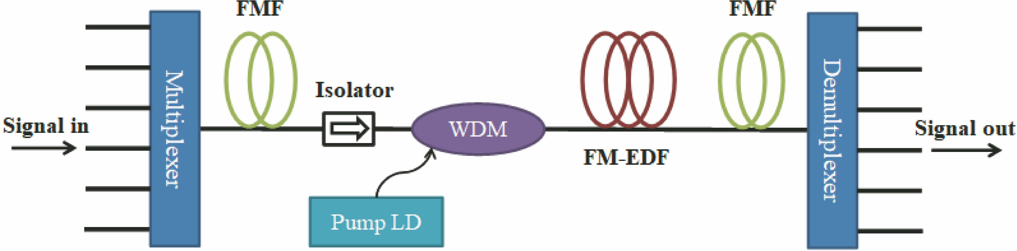
Fig. 1. Schematic diagram of FM-EDFA
![Typical structure of MC-EDFA with fiber-core pumping[14]](/richHtml/gxxb/2021/41/1/0106001/img_2.jpg)
Fig. 2. Typical structure of MC-EDFA with fiber-core pumping[14]
Fig. 3. Typical structure of MC-EDFA with cladding-pumping[15]
Fig. 4. MC-FM-EDFA with cladding-pumping[16]
Fig. 5. Structure of few-mode erbium-doped fiber amplifier[17]
Fig. 6. Few-mode erbium-doped fiber amplification system with SLM[19]
Fig. 7. Two-mode fiber transmission system[20]. (a) Structural diagram; (b) refractive index difference profile of erbium-doped fiber
Fig. 8. Refractive index profile and mode field distributions of ring core fiber[22]
Fig. 9. Ring-core fibers with different structures. (a) Refractive index distribution and doping structure of ring-core fiber with trench[25]; (b) cross section of ring core erbium-doped fiber[26]
Fig. 10. Different doping profiles
Fig. 11. Doping profile designs. (a) Monolayer doping[27]; (b) multilayer doping with the same doping concentration[28]; (c) multilayer doping with different doping concentrations[29]
Fig. 12. Different multi-core single-mode fibers. (a) 12-core erbium-ytterbium co-doped double-cladding fiber[30]; (b) annular cladding-pumped multi-core erbium-doped fiber[31]
Fig. 13. Schematic diagram of MC-EDFA with hybrid pumping[34]. (a) Single-stage; (b) multi-stage
Fig. 14. Cross section and refractive index distribution of double-cladding six-core three-mode fiber[16]
Fig. 16. Nanopore-assisted double-cladding few-mode fiber[38]
Fig. 17. Variation of gain with transmission distance for four modes. (a) Forward pumping; (b) backward pumping


Set citation alerts for the article
Please enter your email address

© Copyright 2018-2021 | Chinese Laser Press. All Rights Reserved 沪ICP备15018463号-20