• Photonics Research
  • Vol. 10, Issue 4, 905 (2022)
Lihong Hong1, Baoqin Chen1, Chenyang Hu2, and Zhi-Yuan Li1、*
Author Affiliations
  • 1School of Physics and Optoelectronics, South China University of Technology, Guangzhou 510641, China
  • 2Guangdong Jingqi Laser Technology Corporation Limited, Dongguan 523808, China
  • show less
    DOI: 10.1364/PRJ.449297 Cite this Article Set citation alerts
    Lihong Hong, Baoqin Chen, Chenyang Hu, Zhi-Yuan Li. Ultrabroadband nonlinear Raman–Nath diffraction against femtosecond pulse laser[J]. Photonics Research, 2022, 10(4): 905 Copy Citation Text show less
    Principle of NRND generation from the PPLN and CPPLN samples. (a), (b) Schematic diagram of the structural geometry of typical 1D PPLN and CPPLN structures. The poling period of the PPLN sample is 6.96 μm and that of the CPPLN crystal ranges from 24 to 14.8 μm. (c) Calculated distributions of the RLV lines in the PPLN structure. (d) The abundant multiple-band RLVs for the designed CPPLN sample. (e) Schematic experimental setup to study NRND. (f), (g) Original and broadened spectra for the pump laser pulse centered at 1300 nm passing through bare LN crystals with 1 mm and 0.5 mm in thickness, in correspondence to PPLN and CPPLN, respectively.
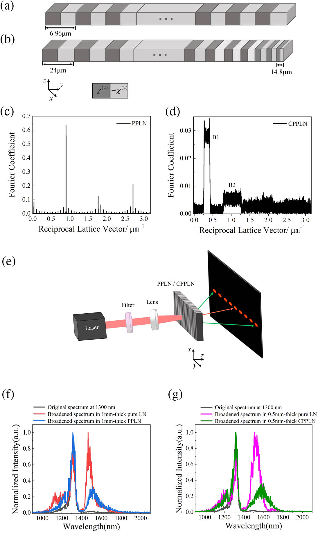
    Fig. 1. Principle of NRND generation from the PPLN and CPPLN samples. (a), (b) Schematic diagram of the structural geometry of typical 1D PPLN and CPPLN structures. The poling period of the PPLN sample is 6.96 μm and that of the CPPLN crystal ranges from 24 to 14.8 μm. (c) Calculated distributions of the RLV lines in the PPLN structure. (d) The abundant multiple-band RLVs for the designed CPPLN sample. (e) Schematic experimental setup to study NRND. (f), (g) Original and broadened spectra for the pump laser pulse centered at 1300 nm passing through bare LN crystals with 1 mm and 0.5 mm in thickness, in correspondence to PPLN and CPPLN, respectively.
    Experimental results of NRND from the PPLN sample. (a) Experimentally recorded multi-order Raman–Nath diffraction patterns in engineered PPLN sample with 1300 nm femtosecond pump laser. (b), (c) Normalized broadband spectra of the Raman–Nath signals emitted from the PPLN sample at different diffraction orders as estimated by a criterion of −20 dB. Note that the spectrum in each panel has been normalized against the maximum value.
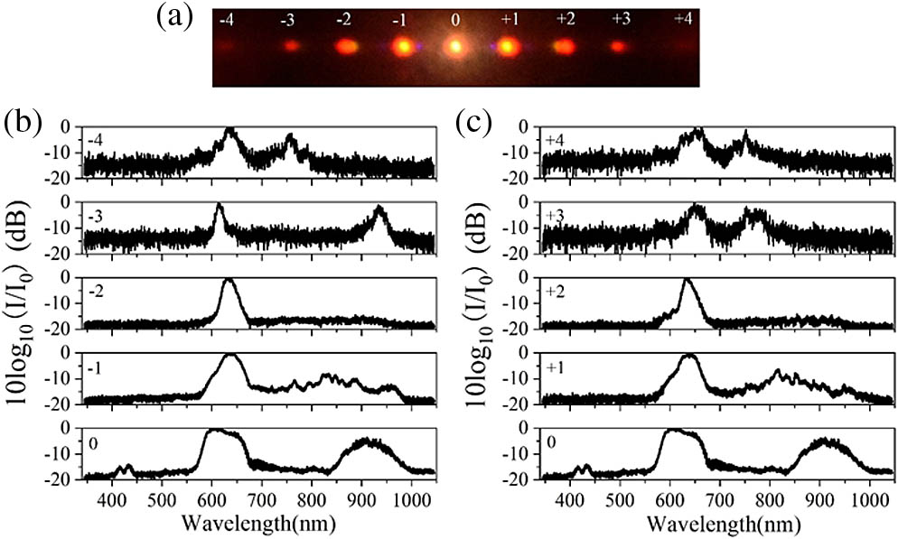
    Fig. 2. Experimental results of NRND from the PPLN sample. (a) Experimentally recorded multi-order Raman–Nath diffraction patterns in engineered PPLN sample with 1300 nm femtosecond pump laser. (b), (c) Normalized broadband spectra of the Raman–Nath signals emitted from the PPLN sample at different diffraction orders as estimated by a criterion of 20  dB. Note that the spectrum in each panel has been normalized against the maximum value.
    Experimental results of NRND from the CPPLN sample. (a) Experimentally recorded multi-order Raman–Nath diffraction patterns in the engineered CPPLN sample with 1300 nm femtosecond pump laser. (b), (c) Normalized broadband spectra of the Raman–Nath signals emitted from the CPPLN sample at different diffraction orders as estimated by a criterion of −20 dB. Note that the spectrum in each panel has been normalized against the maximum value.
    Fig. 3. Experimental results of NRND from the CPPLN sample. (a) Experimentally recorded multi-order Raman–Nath diffraction patterns in the engineered CPPLN sample with 1300 nm femtosecond pump laser. (b), (c) Normalized broadband spectra of the Raman–Nath signals emitted from the CPPLN sample at different diffraction orders as estimated by a criterion of 20  dB. Note that the spectrum in each panel has been normalized against the maximum value.
    Phase-matching diagram of NRND SHG process in the PPLN and CPPLN crystals. (a) Phase-matching diagram for monochromatic Raman–Nath SHG in the PPLN crystal via a single QPM 2nd NL process pumped by the monochromatic light. (b) Phase-matching diagram for multiple broadband Raman–Nath SHG in the PPLN crystal via synergic action of 2nd NL and 3rd NL for the high-peak-power femtosecond pump laser. (c) Phase-matching diagram for monochromatic Raman–Nath SHG in the CPPLN crystal via multiple QPM 2nd NL processes combined with the effect of broadband RLVs. (d) Phase-matching diagram for multiple ultrabroadband Raman–Nath SHG outputs in the CPPLN crystal via synergic action of 2nd NL and 3rd NL combined with multiple QPM interactions.
    Fig. 4. Phase-matching diagram of NRND SHG process in the PPLN and CPPLN crystals. (a) Phase-matching diagram for monochromatic Raman–Nath SHG in the PPLN crystal via a single QPM 2nd NL process pumped by the monochromatic light. (b) Phase-matching diagram for multiple broadband Raman–Nath SHG in the PPLN crystal via synergic action of 2nd NL and 3rd NL for the high-peak-power femtosecond pump laser. (c) Phase-matching diagram for monochromatic Raman–Nath SHG in the CPPLN crystal via multiple QPM 2nd NL processes combined with the effect of broadband RLVs. (d) Phase-matching diagram for multiple ultrabroadband Raman–Nath SHG outputs in the CPPLN crystal via synergic action of 2nd NL and 3rd NL combined with multiple QPM interactions.
    Analysis of angular distribution of multiple-order NRND. (a) External angle of first-order UB-NRND in the CPPLN sample with different poling periods at the pump wavelength of 1300 nm. The red “square” mark represents the external angle corresponding to the average poling period of 18.34 μm. (b) Comparison between predicted and measured angular position for various NRND order parameters for the harmonics emissions from the PPLN and CPPLN samples at the pump wavelength of 1300 nm.
    Fig. 5. Analysis of angular distribution of multiple-order NRND. (a) External angle of first-order UB-NRND in the CPPLN sample with different poling periods at the pump wavelength of 1300 nm. The red “square” mark represents the external angle corresponding to the average poling period of 18.34 μm. (b) Comparison between predicted and measured angular position for various NRND order parameters for the harmonics emissions from the PPLN and CPPLN samples at the pump wavelength of 1300 nm.
    CrystalNegative Diffraction OrderUB-NRND Conversion Efficiency (%)Positive Diffraction OrderUB-NRND Conversion Efficiency (%)
    PPLN−10.03412+10.02970
    −20.09600+20.05933
    −30.01750+30.03017
    −40.00935+40.01275
    CPPLN−10.05308+10.05300
    −20.15667+20.20167
    −30.04317+30.02150
    −40.01017+40.00800
    −50.00377+50.00333
    −60.00143+60.00112
    −70.00077+70.00065
    Table 1. Measured UB-NRND Conversion Efficiency with Different Diffraction Orders in PPLN and CPPLN Crystals
    Lihong Hong, Baoqin Chen, Chenyang Hu, Zhi-Yuan Li. Ultrabroadband nonlinear Raman–Nath diffraction against femtosecond pulse laser[J]. Photonics Research, 2022, 10(4): 905
    Download Citation