• Laser & Optoelectronics Progress
  • Vol. 55, Issue 5, 051204 (2018)
Jun Wang1、1; , Mingli Dong1、1; , Wei Li1、2; , and Peng Sun1、2、1; 2;
Author Affiliations
  • 1 Beijing Key Laboratory of Optoelectronic Test Technology, Beijing Information Science & Technology University, Beijing 100192, China;
  • 1 Institute of Information Photonics and Optical Communications, Beijing University of Posts and Telecommunications, Beijing 100876, China
  • 2 Institute of Information Photonics and Optical Communications, Beijing University of Posts and Telecommunications, Beijing 100876, China
  • show less
    DOI: 10.3788/LOP55.051204 Cite this Article Set citation alerts
    Jun Wang, Mingli Dong, Wei Li, Peng Sun. Photogrammetric Method for Large Trough Solar Reflector[J]. Laser & Optoelectronics Progress, 2018, 55(5): 051204 Copy Citation Text show less
    Binocular stereo camera measurement model
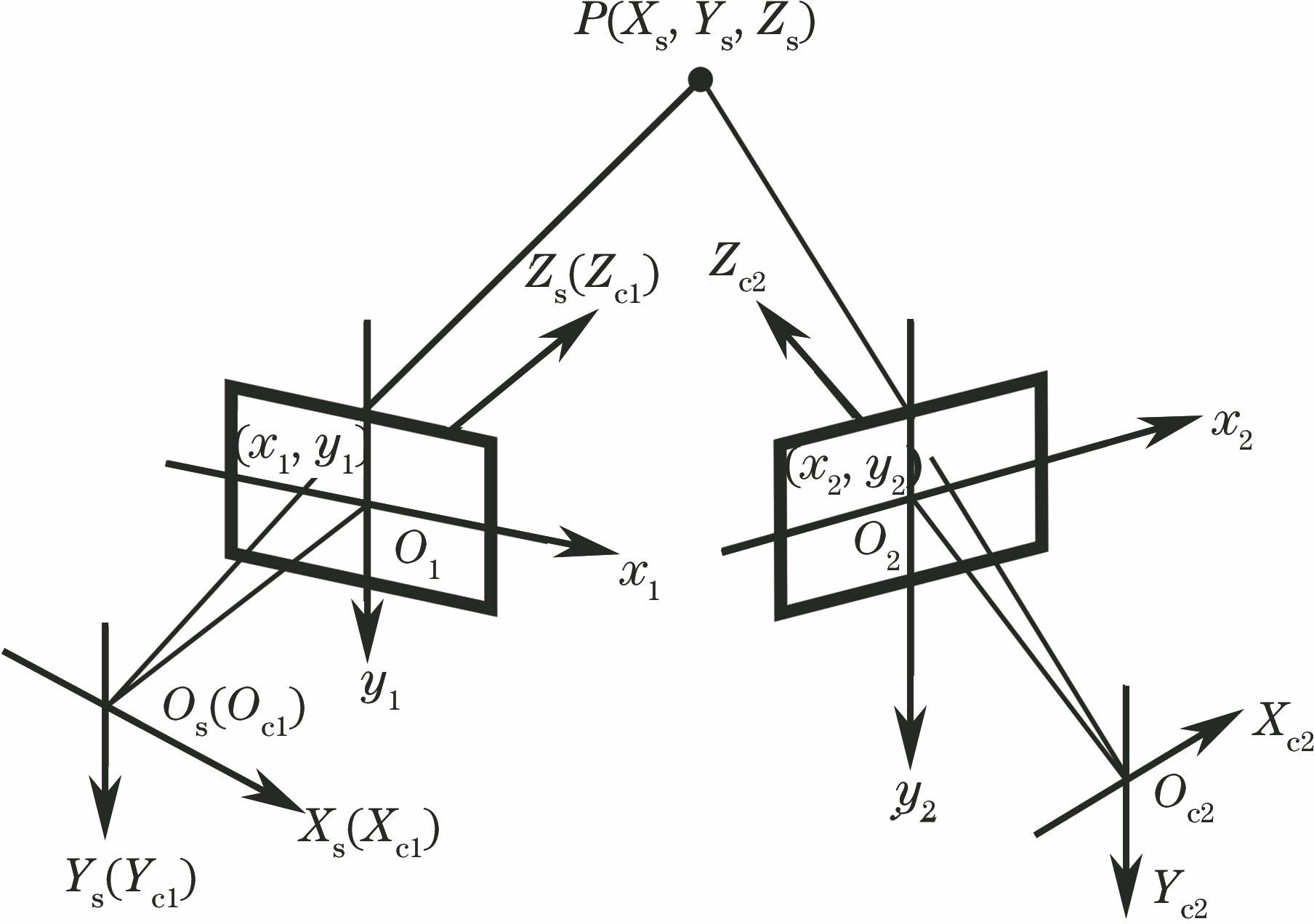
    Fig. 1. Binocular stereo camera measurement model
    Principle of epipolar geometry
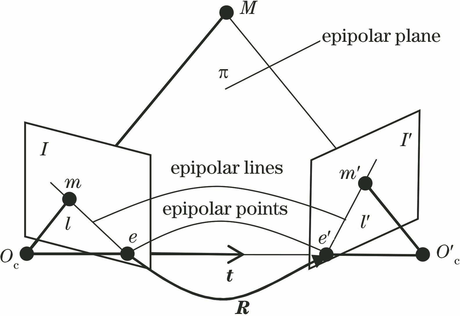
    Fig. 2. Principle of epipolar geometry
    Convex envelope polygon
    Fig. 3. Convex envelope polygon
    Selecting the non-collinear image points on image surface through convex envelope contours detection method. (a) Selecting four vertices of convex envelope; (b) selecting five non-collinear image points; (c) only three vertices of convex envelope
    Fig. 4. Selecting the non-collinear image points on image surface through convex envelope contours detection method. (a) Selecting four vertices of convex envelope; (b) selecting five non-collinear image points; (c) only three vertices of convex envelope
    Flow chart of trough solar reflector surface measurement
    Fig. 5. Flow chart of trough solar reflector surface measurement
    Schematic of cameras extrinsic parameters conversion
    Fig. 6. Schematic of cameras extrinsic parameters conversion
    Larget rough solar reflector surface measurement field
    Fig. 7. Larget rough solar reflector surface measurement field
    Photo taken by the photogrammetric camera (segment)
    Fig. 8. Photo taken by the photogrammetric camera (segment)
    Measurement results of large trough solar reflector surface. (a) Position distribution of the camera; (b) parabolic surface fitting by measuring points
    Fig. 9. Measurement results of large trough solar reflector surface. (a) Position distribution of the camera; (b) parabolic surface fitting by measuring points
    AbsoluteerrorMeanMaximumMinimumStandard
    ΔXt /mm1.0776.5440.0501.881
    ΔYt /mm2.66810.0800.0083.634
    ΔZt /mm1.5877.6990.0121.896
    Δφ /(°)0.0020.07100.015
    ΔΩ /(°)0.0190.19800.024
    Δκ /(°)0.0070.14800.015
    Table 1. Extrinsic parameter absolute error results obtained by relative orientation
    ErrorMeanMaximumMinimumStandard
    ΔX /mm0.0130.0330.0100.003
    ΔY /mm0.0080.0200.0060.002
    ΔZ /mm0.0080.0200.0060.002
    εz /mm1.0505.5470.0051.466
    Table 2. RMS absolute errors of measuring points and εz after bundle adjustment
    Jun Wang, Mingli Dong, Wei Li, Peng Sun. Photogrammetric Method for Large Trough Solar Reflector[J]. Laser & Optoelectronics Progress, 2018, 55(5): 051204
    Download Citation