• Laser & Optoelectronics Progress
  • Vol. 58, Issue 21, 2136001 (2021)
Xuezhi Zhang1、2、3, Guanlong Chen1、2、3, Junfeng Jiang1、2、3、*, Xiaojun Fan1、2、3, Kun Liu1、2、3, Shuang Wang1、2、3, Yantao Liu4, Jingda Ni4, and Tiegen Liu1、2、3、**
Author Affiliations
  • 1School of Precision Instrument and Opto-Electronics Engineering, Tianjin University, Tianjin 300072, China
  • 2Tianjin Optical Fiber Sensing Engineering Center, Institute of Optical Fiber Sensing of Tianjin University, Tianjin 300072, China
  • 3Key Laboratory of Opto-Electronics Information Technology (Tianjin University), Ministry of Education, Tianjin 300072, China
  • 4Beijing Institute of Structure and Environment Engineering, Beijing 100076, China
  • show less
    DOI: 10.3788/LOP202158.2136001 Cite this Article Set citation alerts
    Xuezhi Zhang, Guanlong Chen, Junfeng Jiang, Xiaojun Fan, Kun Liu, Shuang Wang, Yantao Liu, Jingda Ni, Tiegen Liu. [J]. Laser & Optoelectronics Progress, 2021, 58(21): 2136001 Copy Citation Text show less
    Sensing system and WFBG cryogenic properties. (a) Schematic of WFBG-based sensing system; (b) reflection spectra, (c) reflectivity variations, and (d) wavelength shifts of acrylate coated WFBG and bare WFBG at different temperatures
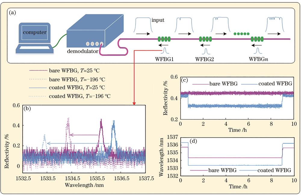
    Fig. 1. Sensing system and WFBG cryogenic properties. (a) Schematic of WFBG-based sensing system; (b) reflection spectra, (c) reflectivity variations, and (d) wavelength shifts of acrylate coated WFBG and bare WFBG at different temperatures
    Influencing factors of optical fiber loss at cryogenic temperature. (a) Schematic of series-connected WFBGs with fusion joints; images of optical fibers with bending diameter of (b) 10 cm at room temperature and with bending diameters of (d) 10 cm, (f) 6.7 cm, and (h) 5 cm at LN2 temperature, corresponding to the reflection spectra of (c), (e), (g), and (i)
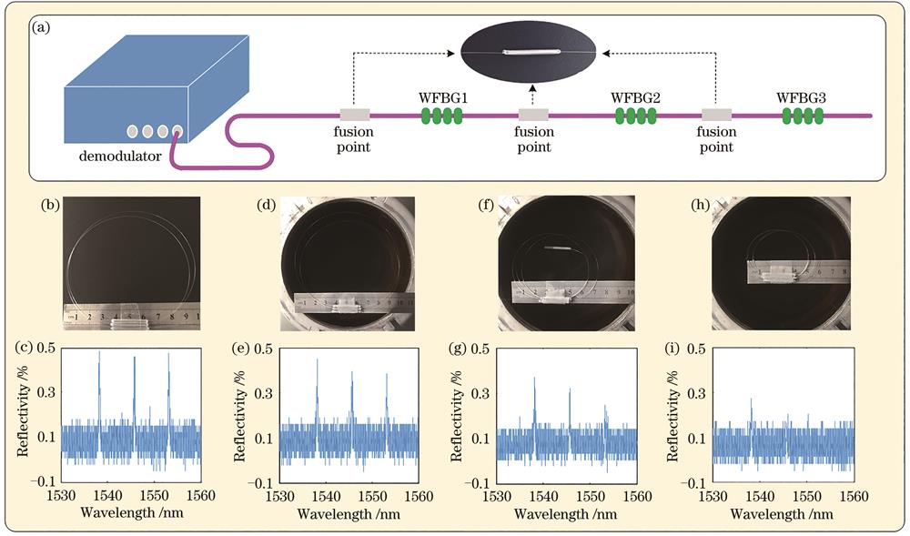
    Fig. 2. Influencing factors of optical fiber loss at cryogenic temperature. (a) Schematic of series-connected WFBGs with fusion joints; images of optical fibers with bending diameter of (b) 10 cm at room temperature and with bending diameters of (d) 10 cm, (f) 6.7 cm, and (h) 5 cm at LN2 temperature, corresponding to the reflection spectra of (c), (e), (g), and (i)
    Encapsulation and calibration of WFBG sensor. (a) Image of a customized strain sensor; (b) substrate encapsulation schematic of strain sensor; (c) tube encapsulation schematic of temperature sensor; (d) quasi-static tensile testing system at cryogenic temperature
    Fig. 3. Encapsulation and calibration of WFBG sensor. (a) Image of a customized strain sensor; (b) substrate encapsulation schematic of strain sensor; (c) tube encapsulation schematic of temperature sensor; (d) quasi-static tensile testing system at cryogenic temperature
    WFBG sensor calibration. (a) Wavelength varying with applied strain in LN2 after second-order polynomial fit of experimental data; (b) wavelength varying with temperature after third-order polynomial fit of experimental data (inset: results near LN2 temperature)
    Fig. 4. WFBG sensor calibration. (a) Wavelength varying with applied strain in LN2 after second-order polynomial fit of experimental data; (b) wavelength varying with temperature after third-order polynomial fit of experimental data (inset: results near LN2 temperature)
    Schematic of test platform for cryogenic static test. (a) Position of oxygen tank in launch vehicle; (b) stress state of oxygen tank during operation; (c) ground test platform for simulating stress state of oxygen tank
    Fig. 5. Schematic of test platform for cryogenic static test. (a) Position of oxygen tank in launch vehicle; (b) stress state of oxygen tank during operation; (c) ground test platform for simulating stress state of oxygen tank
    Loading process of axial force, F1, F2, and internal pressure during pressurization (inset: pressurization schematic).
    Fig. 6. Loading process of axial force, F1, F2, and internal pressure during pressurization (inset: pressurization schematic).
    Strain measurement in cryogenic static test. (a) Hoop strain at bottom of oxygen tank measured by WFBG1 strain sensor (inset: spectrum of three WFBGs); (b) error of hoop WFBG1 sensor; (c) longitudinal strain at welded line on side of oxygen tank measured by "WFBG2" strain sensor (Inset: spectrum of three WFBGs); (d) error of longitudinal "WFBG2" sensor
    Fig. 7. Strain measurement in cryogenic static test. (a) Hoop strain at bottom of oxygen tank measured by WFBG1 strain sensor (inset: spectrum of three WFBGs); (b) error of hoop WFBG1 sensor; (c) longitudinal strain at welded line on side of oxygen tank measured by "WFBG2" strain sensor (Inset: spectrum of three WFBGs); (d) error of longitudinal "WFBG2" sensor
    Temperature variation measured by "WFBG3" temperature sensor (upper inset: reflection spectrum of three WFBGs; lower inset: temperature fluctuation during pressurization)
    Fig. 8. Temperature variation measured by "WFBG3" temperature sensor (upper inset: reflection spectrum of three WFBGs; lower inset: temperature fluctuation during pressurization)
    AdhesiveTensile force /NBonding property
    Epoxy adhesive2.5Poor
    Ceramic adhesive15.6Poor
    Instantaneous adhesive84.2Good

    Instantaneous adhesive+

    epoxy adhesive

    92.8Very good
    Table 1. Bonding property at cryogenic temperature
    Xuezhi Zhang, Guanlong Chen, Junfeng Jiang, Xiaojun Fan, Kun Liu, Shuang Wang, Yantao Liu, Jingda Ni, Tiegen Liu. [J]. Laser & Optoelectronics Progress, 2021, 58(21): 2136001
    Download Citation