Author Affiliations
1School of Precision Instrument and Opto-Electronics Engineering, Tianjin University, Tianjin 300072, China2Tianjin Optical Fiber Sensing Engineering Center, Institute of Optical Fiber Sensing of Tianjin University, Tianjin 300072, China3Key Laboratory of Opto-Electronics Information Technology (Tianjin University), Ministry of Education, Tianjin 300072, China4Beijing Institute of Structure and Environment Engineering, Beijing 100076, Chinashow less
Abstract
In this paper, a weak fiber Bragg grating (WFBG) based sensing system applied to the cryogenic static test of launch vehicle oxygen tanks has been developed and the results of an evaluation are reported. A customized sensor encapsulation and installation method allow for precise strain measurement at cryogenic temperatures. The reflection peaks of series-connected WFBGs with low optical loss are obtained, ensuring high system reliability in harsh environments. The experimental results show that the maximum full-scale error is less than 0.81% full-scale error. The temperature is as low as -193 °C during the test. This study also demonstrates a practical method in which WFBG can be used to obtain critical parameters for structural monitoring in a cryogenic environment.The latest generation of launch vehicles,such as the Proton-M(Russia),Falcon Heavy(American),Ariane series(European),and Long March 5(LM-5)series,is being explored to meet the ever-increasing requirements of satellite clients(China). The design and manufacture of large-scale cryogenic fuel tanks have been considered the challenging aspects of launch vehicle design[1]. Taking LM-5 as an example,it is powered by two 50-t thrust engines which burn liquid hydrogen(LH2)and liquid oxygen(LOX). A large amount of energy necessitates new technologies to increase the fuel tank strength[2-3]. The cryogenic static test must be validated for feasibility and security. The specific process involves applying a load to the fuel tank based on its current stress state during operation. A strain gauge measures the strain at the critical point of the fuel tank. In this manner,the strength of the fuel tank is evaluated by analyzing the state of stress during pressurization at cryogenic temperatures. Hundreds of strain gauges are typically required to cover all measuring points on a fuel tank. Due to the relatively large size of the cable,the measurement system may occupy a large spatial envelope. In addition,electromagnetic interference and short circuits can cause significant errors and even failures[4-6].
| Adhesive | Tensile force /N | Bonding property |
|---|
| Epoxy adhesive | 2.5 | Poor |
| Ceramic adhesive | 15.6 | Poor |
| Instantaneous adhesive | 84.2 | Good |
Instantaneous adhesive+ epoxy adhesive | 92.8 | Very good |
Table 1. Bonding property at cryogenic temperature
As a typical optical fiber sensor,a fiber Bragg grating(FBG)has been extensively studied for parameter monitoring of the launch vehicle fuel tank due to its excellent characteristics such as lightweight,compact size,and immunity to electromagnetic interference[7-8]. One of the first efforts made was to bond FBGs to the LH2 tank for structural health monitoring by NASA and McDonnell Douglas[9-10]. Kang et al. bonded FBG sensors to a filament wound tank and measured strain during the hydrostatic pressurization[11]. Park et al. embedded FBG arrays in a cryogenic composite tank and monitored the strain during insertion of liquid nitrogen(LN2)and pressurization[12]. Furthermore,real-time strain measurement of a composite LH2 tank was performed on a reusable rocket at a height of 42 m. The FBG sensor result was found to be consistent with the strain measured by the strain gauge and the internal pressure of the LH2 tank[13]. The FBG-based strain measurement of the fuel tank had been validated. However,the multiplexing capability of FBG is limited by its high reflectivity(usually greater than 80%),which cannot meet the requirements of large-scale use in the cryogenic static test of fuel tanks[14]. Furthermore,most previous research concentrated on strain measurement in a laboratory at room temperature. Some researchers have investigated strain monitoring at cryogenic temperatures,but this is only a confirmatory experiment,rather than the cryogenic static test required by aerospace standards. In the development of launch vehicles,the strain loading process does not follow the cryogenic static test.
Weak fiber Bragg grating(WFBG)has recently gained popularity due to its extremely low reflectivity,which will greatly increase the multiplexing capacity of sensor arrays[15-17]. Because of their high reflectivity and large operating wavelength range,FBGs can only transmit about ten different wavelengths in a single fiber. When WFBGs are used,the reflectivity of the grating is greatly reduced. As a result,gratings with the same Bragg wavelength can be linked in the same fiber at the same time. Thousands of sensors can be multiplexed in one fiber when combined with time-division multiplexing technology. A large-scale WFBG sensor array combined with optical frequency domain and time domain reflectometry has been one of the hottest research topics in recent years,and it is also a promising solution for cryogenic static testing of fuel tanks[18]. However,the weak reflectivity of WFBG leads to a small amplitude of the reflection peak and a poor signal-to-noise ratio(SNR)of the reflection spectrum. Meanwhile,the cryogenic static test for the large fuel tank of the new generation of the launch vehicle is more complicated due to the high thrust and pressure,which poses challenges for the sensing system. The primary challenge in cryogenic static testing of launch vehicles is that WFBG is exposed to a harsh environment with ultra-low temperatures and high strain. Therefore,it is necessary to study the survivability,reliability,and stability of WFBG in harsh environments of the cryogenic static test.
In this paper,the sensing properties of WFBG are systematically studied in harsh environments. A tailored sensing system is intended to improve the performance of cryogenic large strain measurements. Finally,three WFBGs connected in series with low optical loss are used in the cryogenic static test of the LM-5 oxygen tank,with two WFBGs measuring strain and another WFBG monitoring temperature during the test. The strain measurement errors are analyzed in detail.
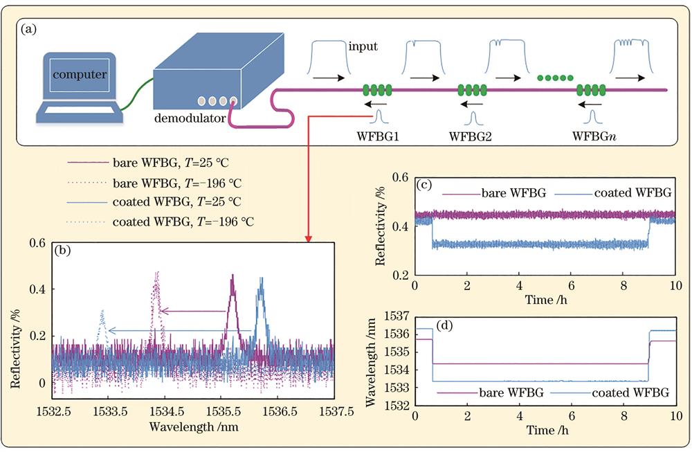
The schematic of the WFBG-based sensing system is shown in Fig. 1(a). The WFBG formed within the optical fiber acts as a notch filter,reflecting light at a wavelength(referred to as the Bragg wavelength)that satisfies the Bragg condition. In one optical fiber line,several WFBGs are connected in series. The reflection spectrum is obtained using a Fabry-Perot filter-based demodulator[19],having a demodulation frequency of 2 Hz,a wavelength stability of 1 pm,8 channels,and a wavelength range of 1525 to 1565 nm. The effects of strain and temperature on the Bragg condition have been widely reported[20] and are exploited in this research. The WFBGs are produced “in-house” using the phase mask method. The UV source is a pulsed 248 nm KrF excimer laser(Coherent BraggStar). A single pulse has an energy of 15 mJ and a duration of 25 ns. WFBGs have a reflectivity of ~0.5% and a full-width half-maximum of 20 pm.

Figure 1.Sensing system and WFBG cryogenic properties. (a) Schematic of WFBG-based sensing system; (b) reflection spectra, (c) reflectivity variations, and (d) wavelength shifts of acrylate coated WFBG and bare WFBG at different temperatures
According to the coupled-mode theory,the reflectivity of the grating is related to the period and refractive index,which is affected by the ambient temperature[21]. However,it is difficult to get an analytical expression due to the complexity of numerical calculation[22]. As a result,in an 8-hour LN2 immersion experiment,the reflectivity and Bragg wavelength of WFBG are investigated. In the experiment,both acrylate coated WFBG and bare WFBG are used. The reflection spectra at room temperature(25 °C)and LN2 temperature(-196 °C)are shown in Fig. 1(b). When the WFBGs are immersed in LN2,the reflection spectra of both the coated and bare WFBGs shift toward the short-wavelength direction. The coated WFBG has a wavelength offset that is roughly twice that of the bare WFBG. It is because that the high thermal expansion coefficient of the acrylate coating improves the temperature sensitivity of WFBG at cryogenic temperatures. Meanwhile,the reflectivity of the coated WFBG is significantly reduced by the ambient temperature,whereas the reflectivity of the bare WFBG is unaffected. The variation in reflectivity during the LN2 immersion is depicted in Fig. 1(c). At room temperature and in LN2,the variation in reflectivity of bare WFBG is less than ±0.04%. Therefore,a bare WFBG should be chosen in cryogenic applications to ensure a high SNR of the reflection spectrum. Based on this result,all subsequent tests in this experiment use bare WFBGs rather than coated WFBGs. The wavelength shift during the LN2 immersion is depicted in Fig. 1(d). Both the reflectivity and wavelength are restored when the WFBGs are taken out from LN2,showing good repeatability. The results also indicate that the WFBG can maintain a stable performance at cryogenic temperatures.
The reliability of the WFBG sensing system in harsh environments is critical due to the cryogenic temperature and large strain of the oxygen tank. The temperature independence of optical fiber loss had been demonstrated[23]. Experiments,however,revealed that at cryogenic temperatures,the loss in optical fiber with fusion joints increases significantly. As a result,three WFBGs are fused in series[see Fig. 2(a)],and the optical loss at cryogenic temperatures is investigated. Heat-shrink tubing protects each fusion joint. The reflection spectra of WFBGs with different optical fiber bending diameters are collected. Figure 2(b)gives the image of the optical fiber with a bending diameter of 10 cm at room temperature. It can be seen from the reflection spectrum in Fig. 2(c)that the reflectivity of the three WFBGs is ~0.5%,without obvious optical loss. As shown in Figs. 2(d),2(f),and 2(h),the optical fiber is immersed in LN2 and the bending diameters are adjusted to 10 cm,6.7 cm,and 5 cm,respectively. Figures 2(e),2(g),and 2(i)show the reflection spectra for the appropriate wavelengths. It can be seen from the reflection spectra in different states that the optical loss is increased significantly with the reduction of the bending diameter. This is because the polyethylene polymer in the heat-shrink tubing is melted and wrapped onto the optical fiber during the heating process. When the optical fiber is placed in a cryogenic environment,the heat-shrink tubing is contracted by cooling. The stress on the optical fiber inside the heat-shrink tubing differs from the stress on the optical fiber outside the heat-shrink tubing. Bending the optical fiber in this manner causes extreme stress at the junction,resulting in the significant optical loss. As a result,when laid in a cryogenic environment,the optical fiber near the fusion joint should be kept as straight as possible. Continuous grating fabrication introduced in Ref.[24],which avoids fusion points,is a preferable solution in large-scale application of WFBG at cryogenic temperature.
Figure 2.Influencing factors of optical fiber loss at cryogenic temperature. (a) Schematic of series-connected WFBGs with fusion joints; images of optical fibers with bending diameter of (b) 10 cm at room temperature and with bending diameters of (d) 10 cm, (f) 6.7 cm, and (h) 5 cm at LN2 temperature, corresponding to the reflection spectra of (c), (e), (g), and (i)
Since the strain in the oxygen tank exceeds the operating range of the WFBG,the WFBG is encapsulated by a customized substrate with small ends and a large middle. Figures 3(a) and 3(b) show the image and encapsulation schematic of the WFBG strain sensor. The strain desensitization degree is related to the length,depth,and height of the substrate. The encapsulation structure is effective in the faithful transmission of strain to WFBG. Figure 3(c)depicts the WFBG temperature sensor encapsulation schematic,which is based on a tube encapsulation. Because of the consistent chemical properties of the low-melting glass and alumina ceramic tubes,the WFBG is protected from a harsh environment.
Figure 3.Encapsulation and calibration of WFBG sensor. (a) Image of a customized strain sensor; (b) substrate encapsulation schematic of strain sensor; (c) tube encapsulation schematic of temperature sensor; (d) quasi-static tensile testing system at cryogenic temperature
The strain calibration is carried out in a cryogenic chamber. The WFBG strain sensor is bonded to an aluminum alloy specimen. There is glue only at both ends of the grating area,and there is no glue in the grating area. As a result,the grating spectrum is guaranteed not to chirp,ensuring that the glue does not affect sensing performance. A quasi-static tensile load is applied to the specimen by a tensile testing machine. As shown in Fig. 3,one side of the tensile testing machine is fixed to the bottom of the cryogenic chamber. The specimen of aluminum alloy is shown in the inset. The cryogenic chamber is filled with LN2 and the strain sensor is immersed in it. Therefore,the temperature of the WFBG is stabilized at -196 °C during the calibration. During the loading process,the Bragg wavelength of WFBG is recorded every 166 με until 4000 με and every 333 με until 0 με during the unloading process. A strain gauge bonded to the other side of the specimen is used to measure the tensile strain. Figure 4(a)shows the strain calibration results. The data is fitted with second-order polynomials with a good quality of fit(the fit coefficient R2 > 0.99906). The fit coefficients are displayed in the figure. A sensitivity of approximately 0.36 pm/με is obtained,which is only one-third of the strain sensitivity of the unencapsulated FBG[25].
Figure 4.WFBG sensor calibration. (a) Wavelength varying with applied strain in LN2 after second-order polynomial fit of experimental data; (b) wavelength varying with temperature after third-order polynomial fit of experimental data (inset: results near LN2 temperature)
The low-melting glass pre-stretches and fixes the two ends of the WFBG in the temperature sensor. At cryogenic temperatures,the low-melting glass performs consistently. As a result,it ensures that the stress on the WFBG remains constant throughout the temperature calibration process and is not affected by strain. The temperature calibration is conducted with an operational range from ~-252 °C to ~50 °C. The sensor is calibrated initially in a Dewar filled with LH2(~-252 °C)similar to the setup used in previous thermal expansion measurements[26]. The WFBG temperature sensor is mounted in close thermal contact with a reference resistive temperature device (RTD). The entire assembly is gradually lowered into a Dewar and submerged in LH2. A diode RTD monitor is used to track the temperature(Stanford Research Systems,SIM923A). The temperature is then calibrated in a variety of settings,including an LN2 tank(~-196 °C),an alcohol bath(~-80 °C and ~-60 °C),and constant temperature oven(~-40 °C,~-10 °C,~20 °C,and ~50 °C). The relation of the temperature and the corresponding Bragg wavelength shift is displayed in Fig. 4(b). The R-squared value of 0.99987 is obtained by a third-order polynomial fit. The sensitivity near LN2 temperature is approximately 2.16 pm/°C[inset in Fig. 4(b)].
The interfacial bond strength between the WFBG sensors and the oxygen tank is the most important factor for accurate measurement. The proper adhesive is selected from several candidates by the so-called pull-off test[27]. The candidates include two-component epoxy adhesive(EP-34B,Kyowa Electronic Instruments Co.,Ltd.),ceramic adhesive(Ceramabond 569,Aremco Products,Inc.),and instantaneous adhesive(CC-33A,Kyowa Electronic Instruments Co.,Ltd.). Two aluminum alloy specimens are bonded together with different adhesives and placed in LN2. After that,the specimens are subjected to a tensile load. Table 1 shows the tensile force generated when cracks form in adhesives. As can be seen,the instantaneous adhesive combined with the epoxy adhesive can withstand a greater load than other candidates. Hence the instantaneous adhesive has been chosen as the primary adhesive for bonding the sensors to the oxygen tank. After fully drying,the epoxy adhesive is then applied to sealing the interfacial bonding.
Based on the research above,the WFBG sensing system is applied to the cryogenic static test of the newly-developed oxygen tank. The oxygen tank is manufactured by using 2219 aluminum alloy with friction stir welding. The diameter is as large as 5 m whereas the thinnest part is only 3 mm.
During operation,the oxygen tank is subjected to internal pressure,resists from the atmosphere,and gravity,and thrusts from the engine and boosters,as illustrated in Figs. 5(a) and 5(b). The ground test platform is constructed following the actual stress state of the oxygen tank,as shown in Fig. 5(c). To control the internal pressure,pure nitrogen is injected. The upper side of the oxygen tank is blocked to simulate the resistance from the atmosphere and gravity. The axial force is applied to simulate the engine thrust. The combined forces of F1 and F2 are applied to simulate the oblique upward thrust of the booster. In the central control room,three WFBGs are linked in series to the demodulator. The WFBGs are labeled “WFBG1”,“WFBG2”,and “WFBG3” according to their optical transmission path. The strain sensor based on WFBG1 is bonded to the bottom of the oxygen tank in the hoop direction. The WFBG2 strain sensor is bonded to the welded line on the side along the longitudinal direction. The WFBG3 temperature sensor is used to monitor the temperature of the oxygen tank surface. The reference strain gauges are also bonded close to the WFBG sensors. The reflection spectrum,strain,and temperature during the test are monitored and saved in real-time.
Figure 5.Schematic of test platform for cryogenic static test. (a) Position of oxygen tank in launch vehicle; (b) stress state of oxygen tank during operation; (c) ground test platform for simulating stress state of oxygen tank
LOX is often replaced by LN2 in aerospace ground tests due to its low temperature and stable physical stability[28]. In this test,1865000 L(49000 cm/s2)LN2 is used to fill the oxygen tank. The pressurized system slowly loads the axial force,F1,F2,and internal pressure. Due to the need for confidentiality,the detailed values are normalized from 0 to 1. The specific loads during pressurization are depicted in Fig. 6. The schematic of pressurization is shown in the inset.
Figure 6.Loading process of axial force, F1, F2, and internal pressure during pressurization (inset: pressurization schematic).
The hoop strain at the bottom of the oxygen tank measured by the WFBG1 sensor and corresponding strain gauge is recorded in Fig. 7(a). Because the detailed data is confidential,the original data is normalized from 0 to 1. During the first 60 min,the load is gradually increased and maintained for about 3 min at each step,resulting in a step-rate line on the strain measured in real-time. The strain gauge and the WFBG1 sensor agree. The strain differences between the WFBG1 sensor and strain gauge are shown in Fig. 7(b). The full-scale error is less than 0.81% full-scale error(FS). The difference between the WFBG sensor and strain gauge may result from a mismatch of sensor angles and locations between them. Although each pair which consists of a WFBG sensor and a strain gauge is bonded at the same location,a small angle difference is inevitable. Figure 7(c)depicts the longitudinal strain at the welded line on the oxygen tank’s side. The combined force of axial force,F1,F2,and internal pressure causes a reverse strain at the measuring point. Fig. 7(d)displays the measurement error. The full-scale error is less than 0.65% of the FS error. The reflection spectra of WFBG1 and WFBG2 sensors are shown in insets in Figs. 7(b) and 7(d). The reflection peaks with large amplitude are obtained by well-designed optical fiber wiring and good protection.
Figure 7.Strain measurement in cryogenic static test. (a) Hoop strain at bottom of oxygen tank measured by WFBG1 strain sensor (inset: spectrum of three WFBGs); (b) error of hoop WFBG1 sensor; (c) longitudinal strain at welded line on side of oxygen tank measured by "WFBG2" strain sensor (Inset: spectrum of three WFBGs); (d) error of longitudinal "WFBG2" sensor
Figure 8 displays the temperature measured by the WFBG3 sensor. It can be seen that the temperature plunges from 35 °C to ~-193 °C during the LN2 injection,and then remains substantially stable. During pressurization,the temperature fluctuates between -193.9 °C and -193.3 °C,as shown in the lower insert. The temperature sensitivity of WFBG near LN2 temperature is approximately 2.16 pm/°C,as shown in Fig. 4(b),so the wavelength drift of the WFBG strain sensor caused by temperature fluctuation is less than 1.3 pm. The measurement error caused by temperature fluctuation is less than 3.6 με for the WFBG strain sensor with a sensitivity of 0.36 pm/με. Given the wide range of the measured strain,the influence of ambient temperature can be ignored. This result is critical for the application of WFBG in cryogenic static tests so that temperature compensation is not required in this case.
Figure 8.Temperature variation measured by "WFBG3" temperature sensor (upper inset: reflection spectrum of three WFBGs; lower inset: temperature fluctuation during pressurization)
In this research,the WFBG is applied to the cryogenic static test of the newly-developed LM-5 oxygen tank. The cryogenic properties of WFBG,optical loss,and adhesive strength are investigated to validate the feasibility of a WFBG-based sensing system in a harsh environment. The customized sensor encapsulation allows for the precise measurement of large strains at cryogenic temperatures. The maximum full-scale errors are 0.81% and 0.65% compared to the reference strain gauges. The measurement error caused by the temperature fluctuation is ignored because the temperature of the tank surface is stable during the test. The experiment results show that the WFBG can pass the cryogenic static test of the oxygen tank. More WFBGs will be used in strain gauges in a single optical fiber line,according to future research. Because the results enable new testing capabilities,the results of this work are also expected to find a wide range of applications. WFBG’s multiplexing capabilities enable the deployment of a spatially dense array of sensors at cryogenic temperatures for superconducting RF cavity characterization,cryogenic piping monitoring,and a variety of other applications.
References
[1] Liu Z, Feng Y Y, Lei G et al. Hydrodynamic performance in a sloshing liquid oxygen tank under different initial liquid filling levels[J]. Aerospace Science and Technology, 85, 544-555(2019).
[2] Higuchi K, Takeuchi S, Sato E et al. Development and flight test of metal-lined CFRP cryogenic tank for reusable rocket[J]. Acta Astronautica, 57, 432-437(2005).
[3] Noorian M A, Haddadpour H, Ebrahimian M. Stability analysis of elastic launch vehicles with fuel sloshing in planar flight using a BEM-FEM model[J]. Aerospace Science and Technology, 53, 74-84(2016).
[4] Jones M. Structural-health monitoring: a sensitive issue[J]. Nature Photonics, 2, 153-154(2008).
[5] Vladimirova T, Bridges C P, Prassinos G et al. Characterising wireless sensor motes for space applications[C], 43-50(2007).
[6] Xu L S, Yang F F, Jiang Y Q et al. Variation of received signal strength in wireless sensor network[C], 151-154(2011).
[7] Yüksel K, Pala D. Analytical investigation of a novel interrogation approach of fiber Bragg grating sensors using Optical Frequency Domain Reflectometry[J]. Optics and Lasers in Engineering, 81, 119-124(2016).
[8] Zhao Y, Liao Y B. Discrimination methods and demodulation techniques for fiber Bragg grating sensors[J]. Optics and Lasers in Engineering, 41, 1-18(2004).
[9] Baumann E W, Becker R S, Ellerbrock P J et al. DC-XA structural health-monitoring system[J]. Proceedings of SPIE, 3044, 195-206(1997).
[10] Ellerbrock P J. DC-XA structural health-monitoring fiber optic-based strain measurement system[J]. Proceedings of SPIE, 3044, 207-218(1997).
[11] Kang H K, Park J S, Kang D H et al. Strain monitoring of a filament wound composite tank using fiber Bragg grating sensors[J]. Smart Materials and Structures, 11, 848-853(2002).
[12] Park S W, Kang S G, Kim M G et al. Structural health monitoring of cryogenic composite tank using embedded fiber Bragg grating sensors[EB/OL]. https://koasas.kaist.ac.kr/handle/10203/148412
[13] Mizutani T, Takeda N, Takeya H. On-board strain measurement of a cryogenic composite tank mounted on a reusable rocket using FBG sensors[J]. Structural Health Monitoring, 5, 205-214(2006).
[14] Flanagan M, Grogan D M, Goggins J et al. Permeability of carbon fibre PEEK composites for cryogenic storage tanks of future space launchers[J]. Composites Part A: Applied Science and Manufacturing, 101, 173-184(2017).
[15] Hu C Y, Wen H Q, Bai W. A novel interrogation system for large scale sensing network with identical ultra-weak fiber Bragg gratings[J]. Journal of Lightwave Technology, 32, 1406-1411(2014).
[16] Luo Z H, Wen H Q, Guo H Y et al. A time- and wavelength-division multiplexing sensor network with ultra-weak fiber Bragg gratings[J]. Optics Express, 21, 22799-22807(2013).
[17] Hu C Y, Wen H Q, Bai W. A novel interrogation system for large scale sensing network with identical ultra-weak fiber Bragg gratings[J]. Journal of Lightwave Technology, 32, 1406-1411(2014).
[18] Han P, Li Z Y, Chen L et al. A high-speed distributed ultra-weak FBG sensing system with high resolution[J]. IEEE Photonics Technology Letters, 29, 1249-1252(2017).
[19] Fan X J, Jiang J F, Zhang X Z et al. Self-marked HCN gas based FBG demodulation in thermal cycling process for aerospace environment[J]. Optics Express, 26, 22944-22953(2018).
[20] de Baere I, Luyckx G, Voet E et al. On the feasibility of optical fibre sensors for strain monitoring in thermoplastic composites under fatigue loading conditions[J]. Optics and Lasers in Engineering, 47, 403-411(2009).
[21] Halstuch A, Westreich O, Sicron N et al. Femtosecond laser inscription of Bragg gratings on a thin GaN film grown on a sapphire substrate[J]. Optics and Lasers in Engineering, 109, 68-72(2018).
[22] Hill K O, Meltz G. Fiber Bragg grating technology fundamentals and overview[J]. Journal of Lightwave Technology, 15, 1263-1276(1997).
[23] Jiang J F, Song L Y, Liu T G et al. Performance characterization of fiber Bragg grating thermal response in space vacuum thermal environment[J]. Review of Scientific Instruments, 84, 123107(2013).
[24] Wang Y M, Gong J M, Dong B et al. A large serial time-division multiplexed fiber Bragg grating sensor network[J]. Journal of Lightwave Technology, 30, 2751-2756(2012).
[25] Arsenault T J, Achuthan A, Marzocca P et al. Development of a FBG based distributed strain sensor system for wind turbine structural health monitoring[J]. Smart Materials and Structures, 22, 075027(2013).
[26] Neely L A, Kochergin V, See E M et al. Negative thermal expansion in a zirconium tungstate/epoxy composite at low temperatures[J]. Journal of Materials Science, 49, 392-396(2014).
[27] Etches J A, Fernando G F. A method to measure the interfacial shear stress for optical fibres embedded in fibre reinforced composites[J]. Advanced Composites Letters, 11, 096369350201100(2002).
[28] Kinefuchi K, Sarae W, Umemura Y et al. Investigation of cryogenic chilldown in a complex channel under low gravity using a sounding rocket[J]. Journal of Spacecraft and Rockets, 56, 91-103(2019).