• Advanced Photonics Nexus
  • Vol. 2, Issue 1, 016005 (2023)
Sven Ebel1、2, Yadong Deng1, Mario Hentschel3, Chao Meng1, Sören im Sande1, Harald Giessen3, Fei Ding1、*, and Sergey I. Bozhevolnyi1、*
Author Affiliations
  • 1University of Southern Denmark, Center for Nano Optics, Odense, Denmark
  • 2Kiel University, Institute for Experimental and Applied Physics, Kiel, Germany
  • 3University of Stuttgart, Research Center SCoPE, 4th Physics Institute, Stuttgart, Germany
  • show less
    DOI: 10.1117/1.APN.2.1.016005 Cite this Article Set citation alerts
    Sven Ebel, Yadong Deng, Mario Hentschel, Chao Meng, Sören im Sande, Harald Giessen, Fei Ding, Sergey I. Bozhevolnyi. Optical reflective metasurfaces based on mirror-coupled slot antennas[J]. Advanced Photonics Nexus, 2023, 2(1): 016005 Copy Citation Text show less
    (a) Schematic of the basic MCSA unit cell consisting of a slot antenna on top of an SiO2 spacer and an Au mirror. (b) Numerically calculated complex reflection coefficients as a function of the slot antenna lateral dimensions at the design wavelength of λ=785 nm upon TM polarization. The SiO2 spacer thickness is set to ts=130 nm. The amplitude |rxx| is visualized by the color map, while the dashed blue lines are the contours of the reflection phase φxx ascending by a 20-deg phase step. (c) Cross-sectional electric field distributions in different cutting planes for the slot antenna with Lx=40 nm and Ly=150 nm at λ=785 nm. The selected cutting planes display the mode profiles within the center of the slot antenna in the top Au layer. The color bars are chosen for illustrating the mode amplitude profiles of the Ex-component, while arrows indicate the electric field vectors at a representative moment of time.
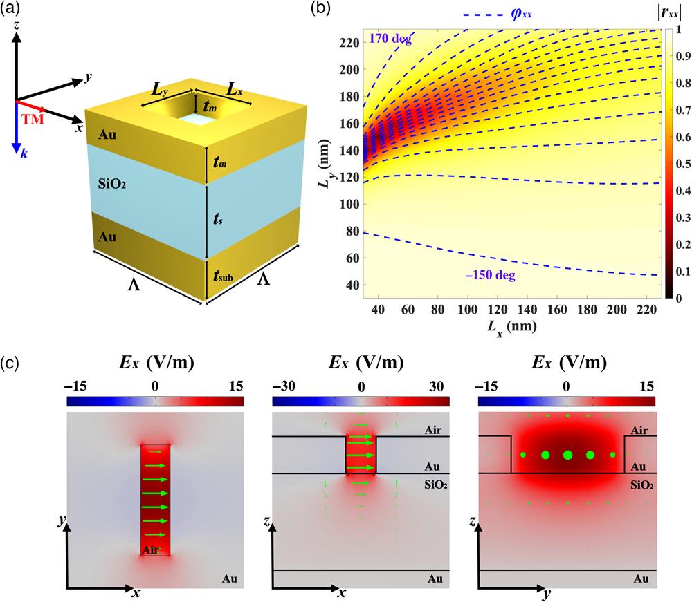
    Fig. 1. (a) Schematic of the basic MCSA unit cell consisting of a slot antenna on top of an SiO2 spacer and an Au mirror. (b) Numerically calculated complex reflection coefficients as a function of the slot antenna lateral dimensions at the design wavelength of λ=785  nm upon TM polarization. The SiO2 spacer thickness is set to ts=130  nm. The amplitude |rxx| is visualized by the color map, while the dashed blue lines are the contours of the reflection phase φxx ascending by a 20-deg phase step. (c) Cross-sectional electric field distributions in different cutting planes for the slot antenna with Lx=40  nm and Ly=150  nm at λ=785  nm. The selected cutting planes display the mode profiles within the center of the slot antenna in the top Au layer. The color bars are chosen for illustrating the mode amplitude profiles of the Ex-component, while arrows indicate the electric field vectors at a representative moment of time.
    (a), (b) Numerically calculated complex reflection coefficients as a function of the slot antenna’s lateral dimensions at the design wavelength of λ=785 nm upon TM polarization. The amplitude |rxx| is visualized by the color map, while the dashed blue lines are the contours of the reflection phase φxx ascending by (a) a 20-deg phase step and (b) a 10-deg phase step. The SiO2 spacer thickness is set to ts=50 nm in (a) and ts=10 nm in (b). (c), (d) Cross-sectional electric field distributions in different cutting planes for the slot antenna at λ=785 nm. The selected cutting planes display the mode profiles within the center of the slot antenna in the top Au layer. The color bars are chosen for illustrating the mode amplitude profiles of the Ex-component, while arrows indicate the electric field vectors at a representative moment of time. (c) The SiO2 spacer thickness is set to ts=50 nm and the slot-antenna dimensions are Lx=40 nm and Ly=150 nm. (d) The SiO2 spacer thickness is set to ts=10 nm and the slot-antenna dimensions are Lx=150 nm and Ly=230 nm.
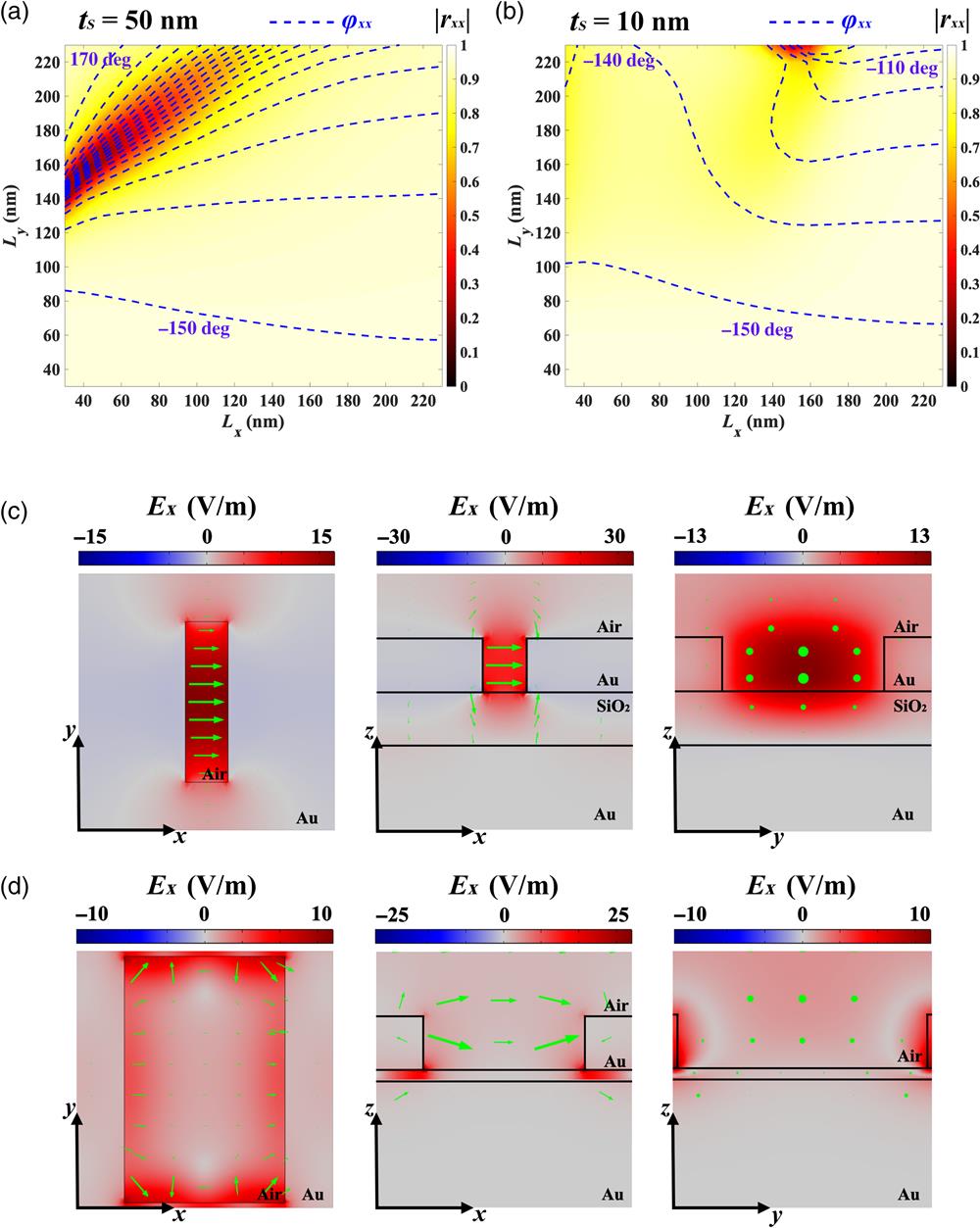
    Fig. 2. (a), (b) Numerically calculated complex reflection coefficients as a function of the slot antenna’s lateral dimensions at the design wavelength of λ=785  nm upon TM polarization. The amplitude |rxx| is visualized by the color map, while the dashed blue lines are the contours of the reflection phase φxx ascending by (a) a 20-deg phase step and (b) a 10-deg phase step. The SiO2 spacer thickness is set to ts=50  nm in (a) and ts=10  nm in (b). (c), (d) Cross-sectional electric field distributions in different cutting planes for the slot antenna at λ=785  nm. The selected cutting planes display the mode profiles within the center of the slot antenna in the top Au layer. The color bars are chosen for illustrating the mode amplitude profiles of the Ex-component, while arrows indicate the electric field vectors at a representative moment of time. (c) The SiO2 spacer thickness is set to ts=50  nm and the slot-antenna dimensions are Lx=40  nm and Ly=150  nm. (d) The SiO2 spacer thickness is set to ts=10  nm and the slot-antenna dimensions are Lx=150  nm and Ly=230  nm.
    Theoretical performance of the beam-steering MCSA metasurfaces that reflect the normal incident TM-polarized light into the +1 diffraction order for supercells consisting of (a) pair, (b) triple, and (c) quadruple identical MCSA meta-atoms. The left columns display the simulated diffraction efficiencies of different orders as a function of wavelength. The right columns show the electrical field distributions at the x–y plane cut from the center of the top slot-antenna layer at the wavelength of λ=785 nm.
    Fig. 3. Theoretical performance of the beam-steering MCSA metasurfaces that reflect the normal incident TM-polarized light into the +1 diffraction order for supercells consisting of (a) pair, (b) triple, and (c) quadruple identical MCSA meta-atoms. The left columns display the simulated diffraction efficiencies of different orders as a function of wavelength. The right columns show the electrical field distributions at the xy plane cut from the center of the top slot-antenna layer at the wavelength of λ=785  nm.
    (a) Schematic illustration of the MCSA reflective metasurface for beam steering. (b) SEM images of the fabricated beam-steering metasurface. The lower image depicts the fabricated supercells. (c) Simulated (solid lines) and experimental (dots with error bars) diffraction efficiencies of different orders as a function of wavelength for TM incident light. The error bars denote the standard deviation of the measured data of four metasurface samples. The inset image shows the diffracted light spots at λ=790 nm, whose intensity has been adjusted for the visualization.
    Fig. 4. (a) Schematic illustration of the MCSA reflective metasurface for beam steering. (b) SEM images of the fabricated beam-steering metasurface. The lower image depicts the fabricated supercells. (c) Simulated (solid lines) and experimental (dots with error bars) diffraction efficiencies of different orders as a function of wavelength for TM incident light. The error bars denote the standard deviation of the measured data of four metasurface samples. The inset image shows the diffracted light spots at λ=790  nm, whose intensity has been adjusted for the visualization.
    (a) Schematic illustration of the MCSA reflective metasurface for beam splitting. (b) SEM images of the fabricated beam-splitting metasurface. The lower image shows the designed and fabricated supercells. (c) Simulated (solid lines) and experimental (dots with error bars) diffraction efficiencies of different orders as a function of wavelength for TM incident light. The error bars denote the standard deviation of the measured data of four metasurface samples. The inset image shows the diffracted light spots at λ=790 nm, whose intensity has been adjusted for the visualization.
    Fig. 5. (a) Schematic illustration of the MCSA reflective metasurface for beam splitting. (b) SEM images of the fabricated beam-splitting metasurface. The lower image shows the designed and fabricated supercells. (c) Simulated (solid lines) and experimental (dots with error bars) diffraction efficiencies of different orders as a function of wavelength for TM incident light. The error bars denote the standard deviation of the measured data of four metasurface samples. The inset image shows the diffracted light spots at λ=790  nm, whose intensity has been adjusted for the visualization.
    Sven Ebel, Yadong Deng, Mario Hentschel, Chao Meng, Sören im Sande, Harald Giessen, Fei Ding, Sergey I. Bozhevolnyi. Optical reflective metasurfaces based on mirror-coupled slot antennas[J]. Advanced Photonics Nexus, 2023, 2(1): 016005
    Download Citation