【AIGC One Sentence Reading】:This study presents a novel, compact system for dual-microcomb generation using a single Si3N4 microresonator, enhancing soliton existence range and paving the way for advanced ranging and low-noise microwave applications.
【AIGC Short Abstract】:This study presents a novel approach for dual-microcomb generation using a single Si3N4 microresonator, pumped by a continuous-wave laser. The method mitigates thermal instability and system complexity,扩大soliton existence range, and paves the way for dual-microcomb applications in ranging and low phase noise microwave generation. The research offers insights into the microresonator mode interaction mechanism.
Note: This section is automatically generated by AI . The website and platform operators shall not be liable for any commercial or legal consequences arising from your use of AI generated content on this website. Please be aware of this.
Abstract
Microcombs have enabled a host of cutting-edge applications from metrology to communications that have garnered significant attention in the last decade. Nevertheless, due to the thermal instability of the microresonator, additional control devices like auxiliary lasers are indispensable for single-soliton generation in some scenarios. Specifically, the increased system complexity would be too overwhelming for dual-microcomb generation. Here, we put forward a novel approach to mitigate the thermal instability and generate the dual-microcomb using a compact system. This process is akin to mode-division multiplexing, as the dual-microcombs are generated by pumping the dual-mode of a single microresonator with a continuous-wave laser. Both numerical simulations and experimental measurements indicate that this innovative technique could offer a straightforward way to enlarge the soliton existence range, allowing entry into the multistability regime and triggering another microcomb alongside the main soliton pulse. This outcome not only shines new light on the interaction mechanism of microresonator modes but also provides an avenue for the development of dual-microcomb-based ranging and low phase noise microwave generation.
1. INTRODUCTION
The microresonator-based frequency comb (microcomb) [1,2], generated by pumping a continuous-wave (CW) laser into a high- optical microresonator, has gained significant attention in research due to its unparalleled miniaturization. As a type of coherent microcomb, the dissipative Kerr soliton [3] is as a self-reinforcing wave packet that maintains its shape while circulating around a microresonator. It has facilitated numerous applications in communications [4–6], laser ranging [7,8], optical clocks [9], microwave photonics [10–12], and photonic signal processing [13–15]. The dual-microcomb, consisting of two microcombs with slightly different repetition rates , could be utilized to coherently down-convert the signal microcomb to the radio-frequency (RF) by beating it with another soliton microcomb. The large optical spectrum down-conversion factor eliminates the need for high-speed photodetectors. The dual-microcomb scheme has displayed exceptional potential in application scenarios of dual-comb spectroscopy [16,17], RF waveform synthesis [18], Vernier spectrometer [19,20], ranging [21,22], and broadband signal channelization [23,24].
Sign up for Photonics Research TOC. Get the latest issue of Photonics Research delivered right to you!Sign up now
Thermo-optic instability is currently a significant challenge for the generation of the soliton microcomb when the pump enters into the red-detuned regime of integrated optical microresonators. To address this concern, sophisticated techniques were developed to mitigate this effect, including auxiliary laser-assisted thermal compensation [25–31], single-sideband rapid frequency sweeping [32], pump modulation [33,34], and pulse-driven schemes [35,36]. However, excessive implementation of control devices adds complexity to the microcomb generation system. When it comes to dual-microcomb generation, either two sets of single-microcomb generation schemes [37], the use of a single laser to pump two independent microresonators [19,38], or the use of two lasers to pump a single microresonator [39,40], is always employed with a larger system volume.
Therefore, there are insistent demands for compact dual-microcomb generation schemes through only a monochromatically pumped single microresonator. Previous researches have explored dual-microcomb generation through opposite direction pumping [41], spatial mode multiplexing [42], and polarization mode multiplexing [43–45]. However, opposite direction pumping still requires extra acousto-optic modulators (AOMs), and spatial mode multiplexing has only been demonstrated in crystalline resonators. Polarization mode multiplexing with adjacent dual-mode type stands out because multiple modes are widespread in integrated waveguides. Recent studies also prove that the dual-mode scheme could prolong the soliton existence range and simplify the setups [46,47]. Additionally, due to the Kerr nonlinear effect [48,49], the pump laser could enter the multistability regime where one mode overlaps with the second mode so that the dual-microcomb source with different repetition rates could also be realized.
In this work, a novel 50 GHz dual-microcomb generation scheme is proposed and experimentally demonstrated by pumping two adjacent modes in a microresonator with a single CW laser. This scheme could mitigate the photo-thermal effect and enlarge the soliton existence range from only 1.7 to 740 MHz. Furthermore, we not only realize stable generation of a -polarized soliton microcomb and a -polarized primary microcomb but also observe a -polarized soliton microcomb and a -polarized chaotic microcomb. Numerical simulation is also conducted to demonstrate the thermal compensation effect and the capacity for dual-microcomb generation. From an application perspective, the demonstrated dual-microcomb generation technology has the superiority in terms of miniaturization and ease of operation, and it would also pave the way for microwave signal generation and interference-free laser ranging applications.
2. MONOCHROMATICALLY PUMPED DUAL-MODE SCHEME
Figure 1(a) illustrates the concept that the dual-microcomb could be simultaneously generated by driving a single microresonator with a single CW laser field. The cavity transfer function for pumping is illustrated in the inset. Two nearby transverse electric modes (the fundamental mode and the first-order mode) with a small mode frequency spacing could be synchronously triggered by the bistability of Kerr cavities. Specifically, by adjusting appropriate pump power and laser frequency sweep velocity parameters accordingly, both cavity resonance (C-resonance, CW component) and soliton resonance (S-resonance, soliton component) of mode could be overlapped with the S-resonance of mode. Therefore, along with the soliton microcomb of the mode, primary comb, secondary comb, chaotic comb, and soliton comb of mode could also be generated simultaneously when exceeding its modulational instability (MI) threshold, thus forming the desired dual-microcomb.
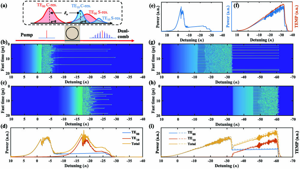
Figure 1.Principle and numerical simulations for dual-microcomb generation with the dual-mode scheme. (a) Theory illustration for dual-microcomb generation with a single pump and two adjacent modes ( mode and mode), in which the C-resonance (C-res.) corresponds to the CW component and the S-resonance (S-res.) corresponds to the soliton component. (b) and (c) are simulated intracavity field evolutions of mode and mode, respectively, without the photo-thermal effect. (d) Numerical simulation of the intracavity powers of mode, mode, and the total without the photo-thermal effect, showing the formation of dual-microcomb. (e), (f) Numerical simulations of the intracavity power evolutions (blue) of single-mode (e) without or (f) with the photo-thermal effect. (f) Temperature-induced resonance frequency variation is indicated by the red line. (g) and (h) are simulated intracavity field evolutions of mode and mode, respectively, with the photo-thermal effect. (i) Numerical simulations of the intracavity powers and temperature-induced resonance frequency variations of mode, mode, and the total with the photo-thermal effect. The simulations reveal the soliton step extension of mode utilizing the dual-mode scheme.
Since there are two modes being pumped, two modified Lugiato-Lefever equations (LLEs) are required to describe the dynamics evolution process of the dual-microcomb in mode and mode, respectively. It is also assumed that the dual-mode resonances could support their own sets of microcomb generation without interaction in the case of large group velocity difference. Moreover, the free spectral range (FSR) difference is out of consideration in the simulation. Additionally, by including a temperature variation in the detuning term, the overall dual-microcomb formation process can be comprehensively understood as below [50,51]: with where is the intracavity field’s envelope, is the total cavity decay rate (with being the intrinsic loss rate and being the external coupling rate), and are the angular frequencies of the pumped cold resonance and the laser, respectively, is the microresonator dispersion, is the thermal resonance shift, is the single photon-induced Kerr frequency shift, is the driving photon flux, is the mode spacing between mode and mode, is the thermal strength coefficient, and is the thermal relaxation time. The subscripts “1” and “2” for the aforementioned parameters correspond to the mode and mode, respectively. Referring to the subsequent experimental characterization results of the microresonator, the partial parameter values in the numerical simulations are as follows: , , , , , and .
Initially, numerical simulation of dual-microcomb generation without the photo-thermal effect (, ) was conducted. Figures 1(b) and 1(c) exhibit the intracavity field evolutions for mode and mode, respectively, and Fig. 1(d) illustrates the intracavity power variations of mode, mode, and the total. It is evident that various Kerr parametric oscillations (primary comb, secondary comb, chaotic comb, and soliton comb) of mode coincidentally exist with the soliton state of mode.
However, owing to the photo-thermal effect, when the microcomb transforms from a high-power chaotic state to a low-power soliton state, the resonator would have a frequency blueshift with a fall of temperature, thus hindering the formation of soliton microcombs. Figures 1(e) and 1(f) showcase the simulation results of intracavity power evolution for single-mode pumping without or with the photo-thermal effect. The temperature-related parameters used are and . The results suggest that the soliton existence range shrinks vastly from to , posing a significant hurdle for soliton microcomb generation. Here, the soliton existence range refers to the frequency range that the pump laser can sweep without losing the soliton microcombs. Fortunately, the monochromatically pumped dual-mode scheme could overcome such thermal instability and diminish the thermal variation when forming solitons within the microresonator. Figures 1(g) and 1(h) show the simulated intracavity field evolutions of mode and mode, respectively, at . This mode spacing is carefully chosen in the simulation process to achieve the best thermal compensation result. Although the soliton step in mode is still extremely short or possibly even negligible, the soliton existence range in mode has been significantly increased from to , which is even greater than that when occurring without the photo-thermal effect.
The reason could be elucidated from Fig. 1(i), which displays intracavity power and temperature-induced resonance frequency variations of mode, mode, and the total cavity. As the microcomb of evolves from the primary comb to the chaotic comb, the intracavity temperature increases gradually and reaches the peak lastly. Once the low-power soliton comb is initiated, the pump laser locates itself at the red side of the resonance frequency, simultaneously cooling the microresonator. Meanwhile, it also enters the blue-detuned and thermal self-lock region of the resonance frequency. By heating up the mode, the total cavity thermal change could be mitigated, thus making the soliton state of the mode more achievable. When the pump laser moves toward the longer wavelength, it could arouse the MI of mode, leading to a simultaneous increase of the total cavity temperature and a decrease of mode resonance frequency. The effective detuning between the pump laser and resonance frequency grows slower than the absolute frequency sweep range of the pump laser itself, which explains why the soliton existence range can be larger than that without photo-thermal effect. As a consequence, our theoretical analysis shows that the monochromatically pumped dual-mode scheme can not only alleviate the microcavity thermal variations and enlarge the soliton existence range but also establish the theoretical principles for dual-microcomb generation.
3. RESULTS AND DISCUSSION
A. Device Characterization and Soliton Step Extension
Figure 2(a) shows the schematic of compact experimental setups for dual-microcomb generation. The CW pump laser used is an external-cavity diode laser with its wavelength around 1550 nm, which can be tuned by a piezo actuated by a ramp voltage signal from an arbitrary waveform generator (AWG). Then, the CW laser is power amplified by an erbium-doped fiber amplifier (EDFA) and filtered by a band-pass filter (BPF) to reject amplified spontaneous emission (ASE) noise from the EDFA. The laser power is subsequently coupled into a silicon nitride () ring microresonator fabricated through a subtractive process [52,53]. The microresonator employed here has a radius of 456 μm and a cross section of μμ. The temperature of the microresonator chip is maintained at 28.50°C by a thermoelectric cooler (TEC). For the microcomb optical output, one part of the microcomb excluding the strong pump by a fiber-Bragg grating (FBG) is detected by a photodiode (PD), followed by an oscilloscope to monitor the power evolution process. The other part is monitored by an optical spectrum analyzer (OSA).
Figure 2.Dual-microcomb generation experimental setups and characterization. (a) Schematic of the experimental setup. The inset shows a microscope image of one fabricated microresonator chip. AWG, arbitrary waveform generator; EDFA, erbium-doped fiber amplifier; BPF, band-pass filter; TEC, thermoelectric cooler; FBG, fiber Bragg grating; PD, photodetector; OSA, optical spectrum analyzer; OSC, oscilloscope. (b) Transmission spectrum of the microresonator used for dual-microcomb generation. The blue and red lines are measured data for and modes, respectively. (c) and (d) are experimentally measured dispersion profiles of and modes, respectively. The blue circles are the measured data, and the red lines are the fitting curves.
Experimentally, we selected the dual-mode in close proximity to each other near 1550 nm for pump by adjusting the polarization state. Figure 2(b) presents a characterization result of the sectional transmission spectrum, which exhibits two sets of TE polarization modes—the fundamental mode and the first-order mode. These modes can be easily distinguished based on the different FSRs. The significantly decreasing extinction ratio near 1550.91 nm indicates a weak mode coupling between the two modes. By extracting and fitting the measured and data [54], the integrated dispersion was calculated and is plotted in Figs. 2(c) and 2(d), respectively. Their FSRs are extracted as 50.024 and 49.316 GHz, respectively, with a difference of that determines the repetition rate difference of the dual-microcomb. Besides, their group velocity dispersion (GVD) was also fitted to be 0.187 and 0.259 MHz, respectively, implying an anomalous GVD that is necessary for soliton generation. It is also mentioned that this dual-mode phenomenon is extensively present in the multimode waveguide with wide cross-section width. Due to the differences in FSR and dispersion, there will be two resonances belonging to different modes that unavoidably cross each other, indicating that the design can be reproduced and fabricated with ease.
Selecting proper mode spacing between mode and mode is crucial for dual-microcomb generation. For overlarge mode spacing, the dual-microcomb will evolve in sequence, and the thermal compensation effect between the dual-mode will never occur. If the mode spacing is too close, only one microcomb can be aroused due to the overlapped transmission spectrum. Figure 3(a) shows the detailed transmission spectrum of the deliberately chosen and pumping modes centered around C34 (channel 34 of the C band, 1550.12 nm) so that the generated microcomb can be easily separated with a commercial wavelength-division demultiplexer. The resonance wavelengths of the two modes are 1550.1134 and 1550.1241 nm, respectively, with the resonance frequency of mode being approximately 1.34 GHz higher than that of the mode. Figures 3(b) and 3(c) show typical and resonance profiles. When a Lorentzian fit is used, it is found that the total cavity decay rates of and were and , indicating loaded values of and , respectively.
Figure 3.Soliton existence range extension through pumping dual adjacent modes. (a) Measured transmission spectrum of and modes for the pump near 1550.12 nm. (b) Microresonator loss results of mode (left) and mode (right), respectively. The blue dots and red lines are the measured results and Lorentzian fits. (c) and (d) are observed soliton steps versus scan time or laser tuning frequency for pumping single-mode and dual-mode, respectively. The inset in (c) is the enlarged soliton step. The soliton existence range is increased obviously from (c) 1.7 MHz to (d) 740 MHz. The frequency-coordinate of (c) and (d) was calibrated by a fiber ring with an FSR of .
As for microcomb generation, the wavelength of the pump laser and the output power of the EDFA are set to and 1380 mW, respectively. The on-chip power is calculated to be about 310 mW considering the 3 dB loss from the band-pass filter and the 3.4 dB loss from the fiber-chip coupling packaging. The microcomb can be excited by scanning the pump laser through the resonant mode from the blue-detuned to the red-detuned side. Here, a simple piezoelectric frequency sweep method [55] is employed with a velocity of . By adjusting the polarization state, when the pumped mode exclusively comprises the fundamental mode, the power evolution of the measured microcomb result is displayed in Fig. 3(c). Due to the thermally-induced resonance frequency shift in the cavity, the soliton state is incapable of existence due to the short soliton step (1.7 MHz), which is consistent with the numerical simulation shown in Fig. 1(f). For the result of the dual-mode scheme presented in Fig. 3(d), the intracavity power evolution reveals two triangular profiles. One represents the Kerr parametric oscillation from the mode, while the other corresponds to the mode. Moreover, the single-soliton step of the mode coincides with the parametric oscillation microcomb of the mode, resulting in a total length of , which is 435 times greater than that of the single-mode approach. As illustrated in Figs. 1(g)–1(i), the mode can mitigate the thermally-induced resonance frequency shift caused by intracavity power change, therefore extending the soliton existence range.
Apart from piezoelectric frequency sweep for soliton microcomb generation, the monochromatically pumped dual-mode scheme could also effectively reduce the thermal variation of the microresonator similar to the auxiliary laser-assisted thermal compensation scheme [25]. The soliton state can be easily reached even by slow temperature control to tune the pump laser wavelength or change the mode resonance frequency according to the photo-thermal effect. As depicted in Fig. 4, here we chose to slowly adjust the temperature of the microcavity chip via a TEC to excite single-soliton microcomb generation. The pump laser is first set to the blue-detuned side of the mode. Then, decreasing the chip temperature from 28.52°C to 28.08°C within 70 s (forward frequency tuning), a multiple-soliton step could be easily accessed as illustrated in Fig. 4(a). Based on the relationship between the chip temperature and the resonance wavelength of [38], the relative frequency sweep velocity is determined to be about 17.8 MHz/s, which is over 5000 times slower than that of the piezoelectric frequency sweep. This illustrates that the Kerr microresonator with a dual-mode scheme is thermally insensitive and the pump laser frequency within the red-detuned side is also allowed. It reveals that the tunable pump laser with relatively high noise could be replaced by an ultra-narrow linewidth laser to improve the coherence of microcomb.
Figure 4.Single-soliton microcomb generation through slow temperature tuning. (a) Microcomb power trace and (b) chip temperature variation under cooling and heating conditions, respectively. The discrete steps suggest different soliton states.
As noted in Ref. [50], a backward frequency tuning strategy could be employed to deterministically achieve the single-soliton state due to the thermal nonlinearity of the Kerr microresonator and the non-degenerate lower boundaries of soliton existence ranges with respect to different soliton numbers. Here, backward frequency tuning is realized by heating the chip from 28.08°C to 28.37°C temperature within 47 s. Therefore, the staircase patterned microcomb power trace can be seen from Fig. 4(a), and each soliton step corresponds to a specific soliton state. The lowest power step is on behalf of the single-soliton state and could be kept stable.
B. Dual-Microcomb Generation and RF Beat Note Analysis
Back to the piezoelectric frequency sweep method, several experimental tests for microcomb generation were conducted by repeatedly scanning the pump laser over the dual-mode region at . Five representative intracavity power results are recorded in Fig. 5(a), which is consistent with the numerical simulation results presented in Figs. 1(g)–1(i). Besides the single-soliton that was already shown in Fig. 3(d), zero-soliton and multiple-solitons with to 4 are also obtained, according to the linear relation between soliton numbers and the detected microcomb power voltage at position ①, where only a single microcomb exists. Figure 5(c) shows the single-soliton microcomb spectrum of a 50 GHz mode spacing measured with an OSA, which is well fitted by the function. The spectrum’s 3 dB bandwidth is roughly 29.47 nm, corresponding to a Fourier-transform-limited pulse duration of 85 fs. The spectrum of the two-soliton state shown in Fig. 5(d) indicates a soliton separation of , retrieved via inverse Fourier transform of the optical spectrum. Furthermore, Figs. 5(e) and 5(f) are the corresponding spectra for and 4, respectively.
Figure 5.Experimental soliton results. (a) Collected powers of microcombs for -, 1-, 2-, 3-, 4-soliton states of 50 GHz mode spacing at . ①, ②, ③, ④ represent different frequency positions for dual-microcomb generation. (b) Principle of the dual-microcomb generation when considering the microcavity thermal effect. (c)–(f) Optical spectra for -, 2-, 3-, 4-soliton states at ① position. The red lines show a fitted envelope (single-soliton) and a fitted 2-soliton envelope type, respectively. The inset of (d) shows the relative soliton position. (g) Statistics of soliton numbers with 30 repeated microcomb excitation processes at , 325 mW, and 380 mW, respectively.
Figure 5(g) records the statistical results of soliton numbers with 30 repeated experimental scanning processes at three different on-chip pump power levels. At , though the success rate for soliton microcomb generation is only 40%, the majority of the microcombs are the two-soliton microcomb and single-soliton microcomb, making them suitable for microwave photonics and other applications. As for and 380 mW, both success rates can reach 100%. Specifically, soliton numbers are distributed from to 6 with on-chip power of 325 mW, whereas multiple-solitons are mainly found from to 7 at . As the pump laser power increases, the success rate for soliton microcomb generation and the soliton numbers would improve as well. The reason can be that the increase in pump laser power could cause more thermally-induced red-shift of the resonance frequency, leading to a decrease in the frequency interval between the triangular profile peak of mode and the resonant frequency mode of . At this point, the mode could further help alleviate the thermal change within the cavity, and the pump laser is more likely to stay at the closer red-shift side of mode resonance, thus leading to multiple-soliton microcomb generation and achieving a higher excitation success rate.
When tuning the pump laser to positions ②, ③, and ④ within the second triangular profile of the intracavity power, the dual-microcomb could appear in different states. As can be seen from Figs. 6(a)–6(c), the dual-microcomb evolves from a single-soliton, primary comb (②) to a single-soliton, secondary comb (③), and eventually to a single-soliton, chaotic comb (④). Moreover, the dual-microcomb could remain stable for at least 2 h without any active feedback technique, which meets the majority of application requirements. It also demonstrates that the chaotic state of the mode with high and unstable energy does not affect the soliton state of the mode. Due to the thermal instability, the second microcomb generated from the Kerr parametric oscillation of mode failed to reach soliton state in the experiment. The illustration in Fig. 5(b) shows that, when considering the microcavity thermal effect, S-resonance of the mode is solely covered with the C-resonance of the mode, while the S-resonance of the mode cannot be reached.
Figure 6.Dual-microcomb spectra and RF beat notes. (a)–(c) Different dual-microcomb optical spectra at ② (single-soliton and primary comb), ③ (single-soliton and secondary comb), and ④ (single-soliton and chaotic comb) positions, respectively. (d) RF noise spectra of the soliton and dual-microcomb. The photodiode noise floor is overlapped by that of the single soliton. (e) and (f) are corresponding 15.5 GHz heterodyne beat notes of the two adjacent lines of the dual-microcomb at ② and ④ positions, respectively.
Figure 6(d) plots the RF noise spectra of various microcombs, which were measured through an electrical spectrum analyser (ESA) by detecting the microcombs excluding the pump line. As for single-soliton or single-soliton, primary comb, the RF noise levels are equal to the background noise levels, showcasing the high coherence of microcombs. However, the yellow line in the RF noise spectra highlights the chaotic nature of the single-soliton, chaotic comb dual-microcomb. Moreover, microwave signals can be extracted from the dual-microcomb by heterodyning a pair of comb teeth with a tunable BPF ( bandwidth). As shown in Fig. 6(a), the first tooth of the primary comb and the 22nd tooth of the single-soliton microcomb are filtered and detected by the high-speed detector. An RF amplifier with signal gain is employed for signal amplification, although the combs used for beating are far from the pump laser, which may deteriorate the linewidth result to some extent. Figure 6(e) shows the collected 15.54 GHz signal with 3 dB bandwidth of with a resolution bandwidth (RBW) of 300 Hz. It proves that the single-soliton and primary comb still has a high coherence with each other. Further, all-optical locking could be considered to improve the mutual coherence. The FSR difference between and modes can be deduced as , which is similar to that of characterization. Moreover, due to the Vernier effect, the second and even more lines of the primary comb could also beat up with the single-soliton to generate different coherent microwave signals such as and (for ).
For the single-soliton & chaotic comb, Fig. 6(f) shows the heterodyne beat note result at the same filtered region, which has a wider 3 dB bandwidth of on a high noise floor. The chaotic comb has been recently applied in various applications such as interference-free LiDAR [22,56,57], optical chaos communication [58], and random number generation [59] depending on its optical spatiotemporal chaos characterization. Compared to the chaotic comb, the single-soliton here could be regarded as a local oscillator light to realize parallel down-conversion for different pairs of the dual-microcomb teeth. For the dual-microcomb, both in the soliton state, which could be used in the dual-comb spectroscopy if assisted by the method of pump modulation, or adopting microresonators with higher in the future, it could also be achieved. In addition, it needs to be mentioned that the conversion efficiency is improved from 0.45% (single-soliton microcomb) to 9.58% (single-soliton and chaotic comb), which illustrates that the dual-microcomb generation with a monochromatically pumped dual-mode microresonator could make the utmost of the pump laser energy.
4. CONCLUSION
In conclusion, we have demonstrated a novel approach to access the 50 GHz dual-microcomb generation via a monochromatically pumped dual-mode microresonator. This scheme has considerable potential toward miniaturization and integration, and it is applicative for other material platforms as well. Both numerical simulations and experimental measurements were conducted to comprehend the mechanisms and forming processes for the dual-microcomb. By taking advantage of the thermal compensation effect from the mode, the soliton existence range of mode could be increased from 1.7 to 740 MHz. It simplifies the soliton excitation procedure with either piezoelectric frequency sweeping or slow temperature control. Besides, dual-microcombs of the mutual-coherent soliton, primary microcomb and incoherent soliton, chaotic microcomb are verified with both spectral analysis and RF beat note measurements. For further practical applications, the dual-microcomb with different polarization modes ( and ) could be separated by the compact inversely-designed silicon photonics device [60]. Furthermore, the methods presented in this study could serve as motivation for studying the interaction mechanism of microresonator modes in Kerr microcomb generation.
Acknowledgment
Acknowledgment. The Si3N4 chips used in this work were fabricated by Qaleido Photonics.
[44] H. Weng, A. Afridi, M. McDermott. Dual-microcombs generation with a single-pumped Si3N4 microresonator for tunable microwave oscillation. CLEO: Applications and Technology, JTu2A.89(2023).
 AI Video Guide
  AI Picture Guide
 AI One Sentence