• Photonics Research
  • Vol. 9, Issue 4, 558 (2021)
Jiachen Li1、2, Baoyu Zhang1、2, Sigang Yang1、2, Hongwei Chen1、2, and Minghua Chen1、2、*
Author Affiliations
  • 1Beijing National Research Center for Information Science and Technology (BNRist), Beijing 100084, China
  • 2Department of Electronic Engineering, Tsinghua University, Beijing 100084, China
  • show less
    DOI: 10.1364/PRJ.412284 Cite this Article Set citation alerts
    Jiachen Li, Baoyu Zhang, Sigang Yang, Hongwei Chen, Minghua Chen. Robust hybrid laser linewidth reduction using Si3N4-based subwavelength hole defect assisted microring reflector[J]. Photonics Research, 2021, 9(4): 558 Copy Citation Text show less
    Schematic diagram of the proposed hybrid narrow-linewidth laser with a Si3N4-based SHDA-MRR as an external feedback cavity butt-coupled with a commercially available DFB laser diode (LD).
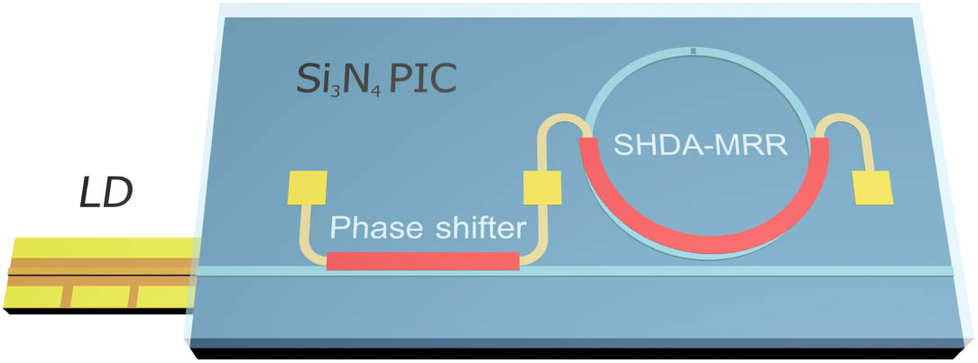
    Fig. 1. Schematic diagram of the proposed hybrid narrow-linewidth laser with a Si3N4-based SHDA-MRR as an external feedback cavity butt-coupled with a commercially available DFB laser diode (LD).
    Schematic diagram of the proposed SHDA-MRR structure (not to scale). A subwavelength hole defect is embedded in the microring waveguide of a conventional all-pass microring resonator for generating manipulated backward scattering and inter-cavity modal coupling between CW and CCW modes.
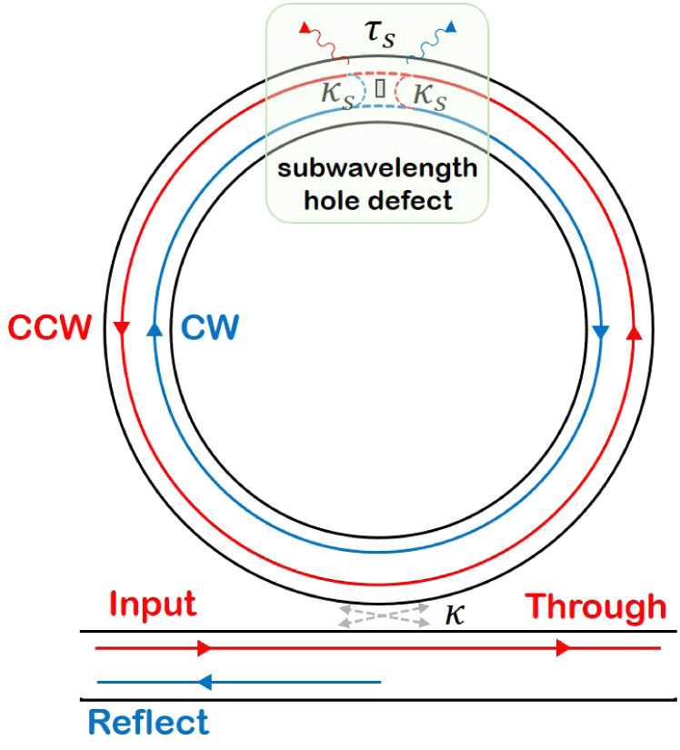
    Fig. 2. Schematic diagram of the proposed SHDA-MRR structure (not to scale). A subwavelength hole defect is embedded in the microring waveguide of a conventional all-pass microring resonator for generating manipulated backward scattering and inter-cavity modal coupling between CW and CCW modes.
    (a) Simulated transmission spectra (including reflection and through responses) of the SHDA-MRR and corresponding reflection response of an add-drop microring reflector (dashed line) for comparison. (b) Simulated reflection responses of the SHDA-MRR with different κs (with κ fixed at 0.2). (c) Comparison of the SHDA-MRR configuration, with the all-pass microring configuration and the add-drop microring configuration. (d) Simulation of κs and τs (at 1543 nm) induced by the subwavelength hole defect with various sizes (the hole-defect length is fixed at 0.2 μm and the hole-defect width is varied from 0.2 to 1.0 μm). (e) κs with the simulation wavelength varying from 1530 to 1570 nm. (f) Schematic diagram of the etched subwavelength hole defect in the waveguide for the simulation in (d) and (e). The simulation is based on the fundamental-TE-mode Si3N4 waveguide (100 nm thick and 2.8 μm wide) with SiO2 cladding, and its mode profile is shown on the right.
    Fig. 3. (a) Simulated transmission spectra (including reflection and through responses) of the SHDA-MRR and corresponding reflection response of an add-drop microring reflector (dashed line) for comparison. (b) Simulated reflection responses of the SHDA-MRR with different κs (with κ fixed at 0.2). (c) Comparison of the SHDA-MRR configuration, with the all-pass microring configuration and the add-drop microring configuration. (d) Simulation of κs and τs (at 1543 nm) induced by the subwavelength hole defect with various sizes (the hole-defect length is fixed at 0.2 μm and the hole-defect width is varied from 0.2 to 1.0 μm). (e) κs with the simulation wavelength varying from 1530 to 1570 nm. (f) Schematic diagram of the etched subwavelength hole defect in the waveguide for the simulation in (d) and (e). The simulation is based on the fundamental-TE-mode Si3N4 waveguide (100 nm thick and 2.8 μm wide) with SiO2 cladding, and its mode profile is shown on the right.
    Optical microscope image of the fabricated Si3N4-based SHDA-MRR chip for the laser linewidth reduction. A subwavelength hole defect with the size 0.5 μm×0.2 μm is etched in the waveguide (bottom, left). Cross section (not to scale) of the employed Si3N4 waveguide platform is also shown (bottom, right).
    Fig. 4. Optical microscope image of the fabricated Si3N4-based SHDA-MRR chip for the laser linewidth reduction. A subwavelength hole defect with the size 0.5  μm×0.2  μm is etched in the waveguide (bottom, left). Cross section (not to scale) of the employed Si3N4 waveguide platform is also shown (bottom, right).
    (a) Measured (dots) and fitted [dashed lines, by Eqs. (1) and (2)] transmission spectra (reflection and through responses) of the fabricated Si3N4-based SHDA-MRR. The inset shows flat multiple reflection resonances from 1542 to 1547 nm, with an FSR of 0.4 nm. (b) Measured (dashed line) and fitted [solid, by Eq. (1)] group delay of the fabricated Si3N4-based SHDA-MRR. (c) Measured reflection resonance tuning across one FSR, with an increased heating power applied to the microheater.
    Fig. 5. (a) Measured (dots) and fitted [dashed lines, by Eqs. (1) and (2)] transmission spectra (reflection and through responses) of the fabricated Si3N4-based SHDA-MRR. The inset shows flat multiple reflection resonances from 1542 to 1547 nm, with an FSR of 0.4 nm. (b) Measured (dashed line) and fitted [solid, by Eq. (1)] group delay of the fabricated Si3N4-based SHDA-MRR. (c) Measured reflection resonance tuning across one FSR, with an increased heating power applied to the microheater.
    (a) Schematic diagram of the experimental setup. A Si3N4-based SHDA-MRR is butt-coupled with a commercially available DFB semiconductor laser for a hybrid narrow-linewidth laser. The output light from the chip is collected and collimated by the micro-lens, and a micro-isolator is placed behind the micro-lens. The inset shows the zoom-in photo of the packaged laser module. The laser output is sent into a DSH setup for the phase noise PSD measurement. LD, laser diode; PD, photodiode; PC, polarization controller; AOM, acousto-optic modulator; OSA, optical spectrum analyzer; ESA, electrical signal analyzer (Agilent E5052). (b) Measured optical spectrum of the hybrid narrow-linewidth laser. The inset shows an SMSR of 50 dB. (c) Single-sided phase noise PSD of the free-running DFB laser and the hybrid laser based on the Si3N4 SHDA-MRR. (d) Frequency noise spectra of the free-running DFB laser (showing a white noise floor of 15,800 Hz2/Hz corresponding to 49.6 kHz intrinsic linewidth) and the hybrid laser based on the Si3N4 SHDA-MRR (showing a white noise floor of 10.9 Hz2/Hz corresponding to 34.2 Hz intrinsic linewidth). (e) Integral phase noise spectra of the free-running DFB laser and the hybrid laser based on the Si3N4 SHDA-MRR calculated from the measured frequency noise spectra. Integral linewidths of 90 kHz and 3 kHz are extracted, respectively.
    Fig. 6. (a) Schematic diagram of the experimental setup. A Si3N4-based SHDA-MRR is butt-coupled with a commercially available DFB semiconductor laser for a hybrid narrow-linewidth laser. The output light from the chip is collected and collimated by the micro-lens, and a micro-isolator is placed behind the micro-lens. The inset shows the zoom-in photo of the packaged laser module. The laser output is sent into a DSH setup for the phase noise PSD measurement. LD, laser diode; PD, photodiode; PC, polarization controller; AOM, acousto-optic modulator; OSA, optical spectrum analyzer; ESA, electrical signal analyzer (Agilent E5052). (b) Measured optical spectrum of the hybrid narrow-linewidth laser. The inset shows an SMSR of 50 dB. (c) Single-sided phase noise PSD of the free-running DFB laser and the hybrid laser based on the Si3N4 SHDA-MRR. (d) Frequency noise spectra of the free-running DFB laser (showing a white noise floor of 15,800  Hz2/Hz corresponding to 49.6 kHz intrinsic linewidth) and the hybrid laser based on the Si3N4 SHDA-MRR (showing a white noise floor of 10.9  Hz2/Hz corresponding to 34.2 Hz intrinsic linewidth). (e) Integral phase noise spectra of the free-running DFB laser and the hybrid laser based on the Si3N4 SHDA-MRR calculated from the measured frequency noise spectra. Integral linewidths of 90 kHz and 3 kHz are extracted, respectively.
    Calculated linewidth reduction factor η [based on Eq. (4)] by simulating different SHDA-MRR reflection responses [based on Eq. (1)] with various κ and κs. With the optimized κ and κs, the hybrid laser based on the Si3N4 SHDA-MRR has the potential to reach a sub-hertz intrinsic linewidth.
    Fig. 7. Calculated linewidth reduction factor η [based on Eq. (4)] by simulating different SHDA-MRR reflection responses [based on Eq. (1)] with various κ and κs. With the optimized κ and κs, the hybrid laser based on the Si3N4 SHDA-MRR has the potential to reach a sub-hertz intrinsic linewidth.
    Jiachen Li, Baoyu Zhang, Sigang Yang, Hongwei Chen, Minghua Chen. Robust hybrid laser linewidth reduction using Si3N4-based subwavelength hole defect assisted microring reflector[J]. Photonics Research, 2021, 9(4): 558
    Download Citation