
Liuhao Zhu, Yuping Tai, Hehe Li, Huajie Hu, Xinzhong Li, Yangjian Cai, Yijie Shen, "Multidimensional optical tweezers synthetized by rigid-body emulated structured light," Photonics Res. 11, 1524 (2023)
- Photonics Research
- Vol. 11, Issue 9, 1524 (2023)
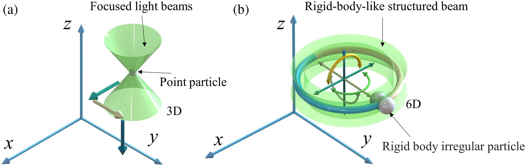
Fig. 1. Concepts of (a) conventional optical tweezers for manipulating mass-point particles and (b) rigid-body emulated structured light tweezers for manipulating irregular objects with full-degree-of-freedom six-axis motion.
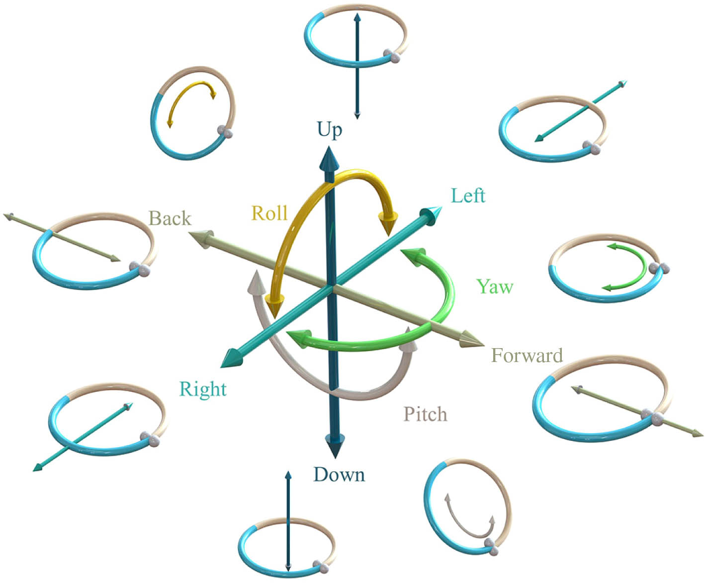
Fig. 2. Schematic of six independent DoFs of the rigid-body mechanics with the structured light trapped particle, including surge, sway, heave, roll, pitch, and yaw.
Fig. 3. Schematic of the experimental setup. L1, concave lens; L2–L5, convex lenses; P1, P2, polarizers; A1, A2, apertures; SLM, spatial light modulator; M1–M4, mirrors; CCD, charge-coupled device; MO1, MO2, micro-objectives. (a) Phase mask diagram, (b) intensity image of captured particle at z = 0
Fig. 4. Steering ability of the beam was verified by manipulating the yeast cells. (a1)–(a5) Images recorded during the experiment, and the parameter of the beam is the spin angle φ = 0 – 2 π φ = 0 – 2 π z Δ z = 0 – 15 μm θ = 0 – 2 π
Fig. 5. (a) 3D model schematic of the TOMOTRAP method. (b) 3D model schematic of the rigid-body emulated optical tweezers. (c) Schematic of the operation of a 3D model of rigid-body optical tweezers. (d) Yeast cells are manipulated by the spin angle φ = 0 – 2 π θ = 7 π / 4 − π / 4 x Δ x = 0 – 20 μm
Fig. 6. CHG of phase masks designed and used in Figs. 4 , 5 , and 7 shown in sub-figures (a1)–(a5), (b1)–(b5), and (c1)–(c5), respectively.
Fig. 7. Yeast capture and flip experiment. (a1)–(a5) Images recorded during the experiment of yeast were captured by changing the precession angle; (b1)–(b5) schematic diagrams of the 3D model corresponding to (a1)–(a5). (c1)–(c5) Images recorded during the experiment of yeast perform a 360° flip; (d1)–(d5) schematic diagrams of the 3D model corresponding to (c1)–(c5).
Fig. 8. (a1)–(a4) Stokes drag force test to determine the trapping force and stiffness of the proposed 6D optical tweezers. (b) Optical trap stiffness versus input power. A polystyrene sphere with a diameter of 3 μm was employed in the experiments.


Set citation alerts for the article
Please enter your email address

© Copyright 2018-2021 | Chinese Laser Press. All Rights Reserved 沪ICP备15018463号-20