1School of Physics and Engineering, Henan University of Science and Technology, Luoyang 471023, China
2State Key Laboratory of Transient Optics and Photonics, Xi’an Institute of Optics and Precision Mechanics, Chinese Academy of Sciences, Xi’an 710119, China
3Shandong Provincial Engineering and Technical Center of Light Manipulations and Shandong Provincial Key Laboratory of Optics and Photonic Device, School of Physics and Electronics, Shandong Normal University, Jinan 250014, China
4Joint Research Center of Light Manipulation Science and Photonic Integrated Chip of East China Normal University and Shandong Normal University, East China Normal University, Shanghai 200241, China
5Optoelectronics Research Centre, University of Southampton, Southampton SO17 1BJ, UK
6Centre for Disruptive Photonic Technologies, School of Physical and Mathematical Sciences and The Photonics Institute, Nanyang Technological University, Singapore 637378, Singapore
Structured light with more extended degrees of freedom (DoFs) and in higher dimensions is increasingly gaining traction and leading to breakthroughs such as super-resolution imaging, larger-capacity communication, and ultraprecise optical trapping or tweezers. More DoFs for manipulating an object can access more maneuvers and radically increase maneuvering precision, which is of significance in biology and related microscopic detection. However, manipulating particles beyond three-dimensional (3D) spatial manipulation by using current all-optical tweezers technology remains difficult. To overcome this limitation, we theoretically and experimentally present six-dimensional (6D) structured optical tweezers based on tailoring structured light emulating rigid-body mechanics. Our method facilitates the evaluation of the methodology of rigid-body mechanics to synthesize six independent DoFs in a structured optical trapping system, akin to six-axis rigid-body manipulation, including surge, sway, heave, roll, pitch, and yaw. In contrast to previous 3D optical tweezers, our 6D structured optical tweezers significantly improved the flexibility of the path design of complex trajectories, thereby laying the foundation for next-generation functional optical manipulation, assembly, and micromechanics.
1. INTRODUCTION
The manipulation of structured light with more extended degrees of freedom (DoFs) and in higher dimensions has recently attracted increasing attention owing to its advanced applications [1,2], which are significant among optical trapping or tweezer technologies with functional structures and increased precision [3,4]. The original optical tweezers can trap particles only at the intersection of six laser beams; the particles are held in a magnetic field by extrusion produced by opposite beams [5]. Since Ashkin discovered that particles can be trapped by gradient forces of light using only one laser beam [6], optical tweezers have been applied in biosciences [7], nanotechnology [8–14], and force measurement [15] as non-contact and noninvasive tools. Usually, conventional single-beam optical tweezers trap particles by using a Gaussian beam. The movement of the trapped particles was performed by moving the sample stage [16] or changing the position of the light spot [17], which endows the optical tweezers with two DoFs (2D manipulation).
In the recent decade, two main techniques have been introduced in optical tweezers to significantly improve the flexibility of manipulation in higher dimensions, that is, digital holography and structured light. Digital holography refers to the acquisition and processing of holograms by a digital sensor array. Holographic optical tweezers were proposed by refreshing phase masks to change the focus position and provide dynamic and digital manipulation modes. These optical tweezers provide flexible manipulation with three DoFs. However, holographic optical tweezers use algorithms to move the optical trap so that its positioning in space depends on spatial parametric equations and the rotation matrix, and it is difficult to freely operate in 3D space because of the limitation of the parametric equation [18]. Holographic optical tweezers rely on the apertures of the mask and elements, which limits the precision of their manipulation [19,20]. Note that the tomographic mold for optical trapping (TOMOTRAP) is a distinguished method that controls the particle’s attitude by analyzing the 3D refractive index of the sample and calculating the corresponding control light field [21]. However, this method is time consuming to determine the sample’s 3D refractive index distribution. Moreover, the trapping capability of this method is constrained by the size of the particles being captured (particle diameters, 2–8 μm).
Owing to the recent emergence of digitally controlled structured light, optical tweezers based on structured light have been endowed with novel capabilities of an optical wrench involving a gradient force, which facilitates novel manipulation modes [22]. Moreover, the structured light based on polarization modulation has been utilized for aligning asymmetric particles [23–26]. In addition to 3D positional trapping, they realized alignment of asymmetric particles. However, it is still a challenge to manipulate particles with three or more DoFs. On the other hand, a vortex beam possesses a spiral phase front that enables the transfer of orbital angular momentum (OAM) to particles, facilitating their rotation and translation. Hence, advanced structured optical tweezers have become a hot topic in optics and photonics [3,4,27]. Considering the rotation of the trapped particle on the structured beam, the existing structured optical tweezers can achieve a fourth DoF of rotation around the optical axis in addition to the three DoF displacements in space [3,28–41]. However, it is almost impossible to further improve the DoFs of manipulation based on the existing schemes. This limitation stems from the traditional view that a trapped particle’s motion appears as a point-like motion in 3D () space. Unfortunately, this perspective does not encompass the complete range of motion modes, which is why six-axis robotic arms and drones have been developed. While we cannot break out of the 3D framework, we can adopt a new approach that views the previous particle model as a rigid-body model. By leveraging novel forms of structured light, we can construct innovative optical tweezers with more DoFs and higher dimensions from this new perspective.
Sign up for Photonics Research TOC. Get the latest issue of Photonics Research delivered right to you!Sign up now
To achieve this goal, we introduce the concept of rigid-body mechanics in optical tweezers and propose 6D structured optical tweezers by tailoring structured light to simulate rigid-body mechanics. This structured light acts as a toroidal ring structure consisting of two semicircular arms with opposing OAMs and an interfering tip to trap particles. When the beam comes into contact with a particle, the particle is trapped at the tip by the ring arm. The combination of the coordinate transformation technique and Fourier transform theorem allows arbitrary rotation and displacement in free space. Six independent DoFs were achieved, and the motions of a six-axis rigid body were conducted, including waves, sway, heave, roll, pitch, and yaw. Therefore, toroidal light can move particles in free space and customize the particle trajectory using the Euler angle in rigid-body mechanics. Finally, we set up an experimental device and designed two experiments to verify the six-DoF modes of motion along arbitrary on-demand spatial trajectories.
2. THEORY
A. Principles and Methods
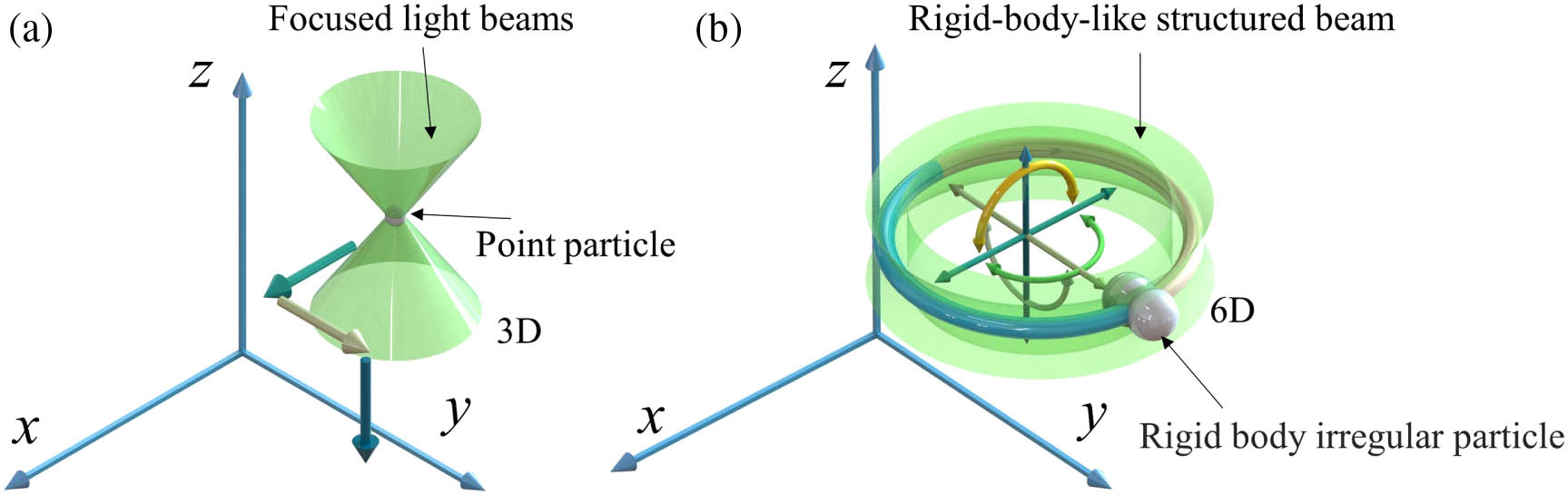
In conventional optical tweezers, the trapped particle is treated as a mass point, the light and particle are treated separately, and only the particle motion state is studied with a maximum of three dimensions, as shown in Fig. 1(a). In our proposed scheme, trapping is treated as a rigid body in which the beam and particle are analyzed as a whole using rigid-body mechanics, as shown in Fig. 1(b). When particles are trapped by gradient forces, they can be moved by moving the beam as holographic optical tweezers [16] or by moving the sample chamber [17]. It seems certain that the particle moving from one point to another can be decomposed into components of motion along the , , and axes. The motion starting at (, , ) can be expressed as where , , and are the initial position coordinates; , , and are the position coordinates after displacement; and , , and are the components of motion relative to the , , and axes, respectively. Equation (1) indicates that there are only three DoFs that describe the motion of the particle, that is, three straight lines along the coordinate axes. This directly limits the DoFs of optical tweezers for particle manipulation, which significantly reduces the richness of the manipulation modes of the optical tweezers. It is well known that the motion of a rigid body in space possesses six DoFs: surge (translation along the axis), sway (translation along the axis), heave (translation along the axis), roll (rotation along the axis), pitch (rotation along the axis), and yaw (rotation along the axis). Analogously, we constructed rigid-body optical tweezers to obtain the motion of particles with six DoFs in space, and the schematic diagram is shown in Fig. 1(b). Six independent DoFs are included in the total complex amplitude for 6D control of structured optical tweezers (, , , , , ), assuming that the ring light tip coordinate is (, , ), and its coordinates can be expressed as where , , and () correspond to the rotation matrices of the , , and axes, respectively. Gaussian beams are not up to the task; thus, structural beams are exploited to solve this issue. Note that the constructed structured light, called rigid-body emulated structured light, possesses the following distinctive characteristics: it is capable of free rotation in 3D space without experiencing any deformation, mimicking the behavior of a rigid body;it can freely rotate and perform various motions in space without the support of additional devices;it can effectively capture particles to form a rigid body for real-time manipulation.
Based on these concepts, as shown in Fig. 1(b), rigid-body optical tweezers are composed of two semicircular vortex beams, represented by two different colors. The two parts carry opposite topological charges (TCs) and produce an interference point at one of the junctions to form a tweezers’ tip to trap particles. The structured light and trapped particle are then considered as a combined rigid body. Its generation and control methods are discussed in detail in Appendix A. Consequently, no matter where the particle is within the range of the rigid-body optical tweezers, it will eventually be trapped at the tip of the tweezers. We treat the combination of the structured beam and particle as a rigid body during manipulation. Therefore, the entire optical tweezers system is endowed with the properties of a rigid body, and the motion of the particle can be regarded as the motion of a fixed point on the rigid body. The surge , sway , and heave of the system can be precisely controlled by the Fourier phase-shift theorem and additional spherical waves as presented in Appendix A.
Figure 1.Concepts of (a) conventional optical tweezers for manipulating mass-point particles and (b) rigid-body emulated structured light tweezers for manipulating irregular objects with full-degree-of-freedom six-axis motion.
To describe and regulate these poses better, we exploit the universal rotation theory of rigid-body Euler angles. Figure 2 shows a schematic of the surge, sway, heave, roll, pitch, and yaw. The six DoFs are indicated by arrows in the subgraphs in different colors. Each subgraph represents the motion of toroidal light for a specific DoF. The Euler angles consist of a nutation angle , precession angle , and spin angle , which correspond to the roll, yaw, and pitch in Fig. 2, respectively. Up to now, optical tweezers have been successfully endowed with these three additional rotation dimensions. According to Schaller’s theorem [42], the displacement of a rigid body can be produced by translation along its screw axis (Mozzi axis) followed by a rotation around an axis parallel to that screw axis. In our case, all rigid-body motions are conducted in two steps: by determining the displacements (, , ) and then executing the rotations (, , ). Finally, the rotation is evenly interpolated into the displacement. It should be noted that the three rotational DoFs do not conform to the law of exchange, which indicates that the rotation order affects the final result. Therefore, we can realize the rigid-body motion of toroidal light involving trapped particles in space, i.e., 6D optical tweezers. Subsequently, we select several paths for verification in the experiments.
Figure 2.Schematic of six independent DoFs of the rigid-body mechanics with the structured light trapped particle, including surge, sway, heave, roll, pitch, and yaw.
To verify the 6D optical tweezers, we set up an experimental device as shown in Fig. 3. The laser beam was amplified by lenses L1 () and L2 () and adjusted into an approximate parallel beam. The 532 nm beam was then intercepted into a flat-top beam by a small aperture A1. Through polarizer P1, linearly polarized light illuminated the spatial light modulator (SLM, HOLOEYE, pixel size, μμ; resolution, pixels) for modulation. The modulated beam was filtered using a system comprising L3 () and L4 (). Finally, toroidal light (st order diffraction) was obtained, which was focused through MO1 (1.2 NA, ) to the sample chamber for particle manipulation. The illumination was red LED light focused through the microscopic objective MO2 (0.4 NA, ). Finally, the charge-coupled device (CCD, Basler acA1600-60gc; pixel size, μμ) recorded the motion of the particles. Polarizer P2 was used to eliminate the green light in the CCD. Yeast cells were selected as samples to highlight their application in biosciences. Toroidal light is generated by holography, and the mask is loaded or switched in the SLM in real time to manipulate the cells.
Figure 3.Schematic of the experimental setup. L1, concave lens; L2–L5, convex lenses; P1, P2, polarizers; A1, A2, apertures; SLM, spatial light modulator; M1–M4, mirrors; CCD, charge-coupled device; MO1, MO2, micro-objectives. (a) Phase mask diagram, (b) intensity image of captured particle at plane, and (c) 3D state model diagram of the captured particle.
Owing to the advantages of the proposed 6D optical tweezers, we could freely customize the motion trajectories of the trapped particles. In this case, three rotational DoFs are expressed by the angle and three displacement DoFs are expressed in micrometers. A set of experiments was designed to verify the capacity of the proposed 6D optical tweezers. In the first experiment, yeast cells with asymmetrical sizes were chosen to confirm the beam’s capability in controlling the direction within the plane (see Visualization 1 for details). The beam parameter used in the experiment was the spin angle , ranging from 0 to . By rotating the beam, we observed that the yeast particles moved in a circular motion, with the larger side of the yeast cell facing outward in the circle [see Figs. 4(a1)–4(a5) and 4(b1)–4(b5)]. In the second experiment, to verify its ability to move along the axis, we still chose the spin angle and the displacement along the axis μ. Under these conditions, the motion trajectory of the captured particles is a 3D spiral. Figures 4(c1)–4(c5) show a part of the screenshot captured in the experiment. Figures 4(d1)–4(d5) show the corresponding 3D model demonstrations. The complete details are presented in Visualization 2. Because the CCD captures a 2D picture, Newton’s rings generated by the diffraction of trapped particles are exploited as a reference to determine the motion of the particles. During the manipulation process, the trapped particle becomes blurred, which is caused by the defocusing of the particle after 3D motion. Owing to the advantage of more DoFs of 6D optical tweezers, a complex 3D spiral trajectory can be designed by adjusting only two parameters. Further, to observe the orientation adjustment in plane (pitch motion), in the third experiment, we randomly selected two bonded yeast cells of different sizes and performed a 180° flip to verify the capability of our technique in adjusting particle orientation. The nutation angle was varied from 0 to as illustrated in Figs. 4(e1)–4(e5). As observed in Fig. 4(e1), particle 1 initially occupies the lower right position. Subsequently, in Fig. 4(e3), particle 1 rotates to the position directly below particle 2, causing it to disappear from the camera’s field of view. Finally, it reappears in the upper left position as shown in Fig. 4(e5). Full details are given in Visualization 3. The results prove that the proposed optical tweezers have the ability to modulate the orientation of trapped particles. Note that the force field applied on the trapped particle should be first studied and analyzed before motions to ensure the conditions of a solid rigid body formed by the trapped particle and the beam for manipulating complex/bulk particles.
Figure 4.Steering ability of the beam was verified by manipulating the yeast cells. (a1)–(a5) Images recorded during the experiment, and the parameter of the beam is the spin angle . (b1)–(b5) Schematics of the 3D model corresponding to the first row. (c1)–(c5) Images recorded when the yeast cells were manipulated by the spin angle and displacement along the axis μ. (d1)–(d5) Schematics of the 3D model corresponding to the third row. (e1)–(e5) Images recorded during the experiment of performing a 180º flip of the yeast cells, and the parameter of the beam is the nutation angle . (f1)–(f5) Schematics of the 3D model corresponding to the fifth row.
Figure 5.(a) 3D model schematic of the TOMOTRAP method. (b) 3D model schematic of the rigid-body emulated optical tweezers. (c) Schematic of the operation of a 3D model of rigid-body optical tweezers. (d) Yeast cells are manipulated by the spin angle , nutation angle , and displacement along the axis μ.
Execution of rigid-body motion of multiple particles is the outstanding advantage of the proposed 6D optical tweezers. For example, of two particles’ rigid-body motion, as depicted in Fig. 5(a), particles 1 and 2 are manipulated from to , and to in 3D space, respectively. During motion, particles 1 and 2 maintain the positions relationship of a rigid body. This is very difficult for previous manipulation techniques, especially the TOMOTRAP method [21] due to single particle manipulation. As shown in Fig. 5(b), it is easy to execute the same manipulation using the proposed rigid-body emulated optical tweezers. To verify the other DoFs and illustrate the directional change of the rigid body, we capture two particles at the same time and design a more complex 3D cycloid path, which is shown in Fig. 5 (for details, see Visualization 4), and three views of this trajectory are shown in the dashed box. The beam is modified to have two tips to accomplish this goal (for details, see Appendix B). For better characterization and comparison, we merged the patterns of the particles in the 3D model and the experimental images into one image at regular intervals. To make the 3D model clearer, the particles were painted in red and blue to highlight their positions, and two arrows of the same color with different orientations were added to indicate the direction. Explicitly, the trajectory of the trapped particle agrees well with the given complex path. In Fig. 5, the numbered sample states are captured successively, where 0 represents the starting state and 10 represents the ending state. The relative distance between the two particles does not change, but the overall orientation keeps changing in the process of movement. The results prove that the proposed 6D optical tweezers can conduct arbitrary combinations of six DoFs.
The capacity of the proposed 6D optical tweezers was greater than that of the conventional tweezers. The trapping range can be controlled by adjusting the radius of toroidal light, whereas the velocity of the particles can be controlled by adjusting the change frequency of the mask or the interval between changes in the DoF parameters (see Appendix B). The experiment of capturing yeast in different planes by changing the precession angle is described in Appendix B. Furthermore, the optical trap stiffness was measured as a standard to evaluate the performance of the proposed optical tweezers. Considering generality, polystyrene spheres were selected for the drag test. The power of the beam before entering the microscope objective prevails, and the test results indicate that the trap stiffness of the particle is proportional to the laser power for a specific particle. When the laser power is 30 mW, the optical trap stiffness is approximately 1.34 pN/μm, which is sufficient to support it to drive most biological cells without causing thermal damage. The details are presented in Appendix B.
For discussion, it is beneficial for readers to compare and review the proposed method with previous manipulation techniques, such as polarization modulation [23–26] and TOMOTRAP. The first and most significant distinction is the mechanism of manipulation. As demonstrated in our experiments, rigidly moving the beam equates to the manipulated particles, which represents a completely new and unprecedented concept.The proposed method greatly simplifies the rigid-body motion manipulation of multiple particles. Compared with the TOMOTRAP method, the proposed method exhibits the manipulation capacity of the smaller particle .Our technique offers a greater DoF in terms of motion control than traditional polarization-based methods.
4. CONCLUSIONS AND OUTLOOK
Our experiments demonstrated the feasibility of using 6D optical tweezers. We also measure the performance parameters of 6D optical tweezers in Appendix B, which lays the foundation for their applications in other fields. In our case, based on the demonstration of trapped particles, only two trajectories were illustrated, but the six-DoF settings of the optical tweezers (in addition to making toroidal light perfectly parallel to the optical axis) were arbitrary. Thus, the velocity and trajectory of the particles can be customized according to researchers’ desires and requirements. In our experiment, the orientation of the multi-particle system can be controlled significantly, and we can achieve a large angle between the toroidal structured beam and the plane (enough to flip the particle 360°; see Appendix B and Visualization 6 for details). These characteristics are not available in traditional 3D optical tweezers. Thus, the realization of six-DoF manipulation means that the limitation of the previous point motion is broken. The freedom to complete six-axis motion means that we can conduct operations similar to macroscopic robotic arms in the microscopic world. With the enhancement of real-time microscopic observation technology to detect such motions of particles, the comprehensive regulation of particle orientation and other attributes can be executed. This study is important in pertaining to the manipulation of particles with complex shapes to enable the next generation of optical tweezers.
The rigid-body-emulated tweezers in toroidal structured light provide extra DoFs for optical tweezers and achieve 6D optical tweezers. The proposed 6D optical tweezers can simultaneously generate multiple interference points with controllable spacing and are not limited to circular beams. Our method can be extended to novel advanced optical tweezers employing other kinds of complex structured light, such as torus knots [43–45], super-toroids [46], and ray–wave vector beams [47–49], which will lead to higher-dimensional control. This scheme is a fundamental platform, based on which even higher-dimensional (7D) optical tweezers can be developed by involving time as an additional DoF. The structured beam on the spatiotemporal scale can cause particles to execute arbitrary circular motions under certain circumstances [50–52], and more dimensions subjoin the optical tweezers by introducing space–time optics. The self-accelerating wave envelopment causes arbitrary temporal control acceleration for the optical field, which creates longitudinally invariant DoFs for optical manipulation [53–55]. Moreover, the introduction of symmetry and nonlinearity of increasingly complex structured light will provide more DoFs and lead to novel applications for complex tweezers and multi-particle manipulation [56–59]. In summary, we devised a basic method to generate higher-dimensional optical tweezers of arbitrary rigid-body objects, paving the way for studying more extreme light–matter interactions in the future.
APPENDIX A: SUPPLEMENTARY THEORY OF 6D TWEEZERS
First, we designed a pair of 2D structured optical tweezers. A structured optical field with an arbitrary curvilinear mode is reported in Ref. [34]. In the initial plane, the beam is represented as where = dominates the shape of the beam, with , and denotes the differential operation. (, , ) and (, , ) are terms that represent the phase of the beam:
Here, is the wavelength of light in the medium, and is the focal length of the lens. is the defocusing distance defined along the curve . The curve is determined by the relations , , and . In this case, a circular curve was selected as the candidate to construct the optical tweezers, and the relationships among these three parameters are as follows: where is the radius of the beam, which is 0.7 mm in our case, except for the stiffness measurement for the optical trap. Optical tweezers were constructed using two semicircles by assigning opposing TCs. The interference petal point is the tip, and the two semicircles are the arms of the optical tweezers [60,61]. 2D optical tweezers have the advantage of a larger trapping range [62]. To realize optical tweezers using the aforementioned structured optical field, we alter the upper and lower integral limits of these two semicircles on the circular curve described by Eq. (A3). Assume that represents the TC magnitude of the beam ( is set as 30 in this case), and the integral limits satisfy . Here, the amplitude of the optical tweezers is determined as where and 2; , and . To ensure that the beam has a closed curve, and . It is worth noting that if we want to get two focal points, we just need to set and . If we need more focal optical tweezers, we can just continue to segment the function.
Intuitively, a pair of real 6D optical tweezers can be obtained via combined translation and rotation operations around the center of the 3D tweezers. After these operations, the tip of the tweezers can theoretically reach an arbitrary position, according to researchers’ desires. First, to better describe and regulate these three dimensions, it is necessary to use the universal rotation theory of the rigid-body Euler angle. The nutation angle and precession angle can be obtained by modifying beam equations and coordinate transformation techniques. The transformed coordinates can be expressed as follows: where () are polar coordinates corresponding to the coordinates of (), and () are coordinates after transformation. Here, in Eqs. (A5) and (A6) can be rewritten as follows:
Substituting Eqs. (A7) and (A8) into Eqs. (A4) and (A5), the roll and pitch can be obtained using this rigid-body beam. Yaw (rotation along the axis) can then be achieved by changing the relationship between and to and . The relation after transformation can be expressed as
Finally, we present the creation of tweezers for the translation of the three axes. The translation in the plane surge and sway can be realized by the Fourier phase-shift theorem, whereas the translation along the axis heave can be realized using additional spherical waves. The beam was shifted in the image plane by adding a phase shift to the object plane. Hence, all these were achieved by changing the phase masks. Therefore, we add plane and spherical waves to its computer-generated hologram (CGH) to execute the manipulation displacement operation: where , , and are the displacements of the surge, sway, and heave, respectively, along , , and axes. Owing to the Fourier displacement theorem, the phase shifts of the plane and spherical waves applied to the hologram become the displacement of toroidal light, which can be obtained as
Six independent DoFs are contained in the total complex amplitude of the 6D structured optical tweezers (, , , , , ). Assuming that the ring light tip coordinate is (, , ), its coordinates can be expressed as
APPENDIX B: DIGITAL GENERATION OF 6D OPTICAL TWEEZERS
To date, tweezers have been successfully transformed into spatial optical tweezers with six DoFs. Before optical tweezer manipulation, it is necessary to clarify the generation method of 6D optical tweezers. In this study, the CGH method was exploited using an SLM. The phase mask is expressed as follows: where is the phase extraction function. Several CGH phase masks of the 6D optical tweezers used in the main text are shown in Fig. 6. The phase masks in Fig. 4 in the main text are shown in the top row of Fig. 6. In the experiment, we generated 100 phase masks and refreshed the masks at a rate of 0.5 s for the purpose of particle manipulation. Here, the refresh rate and interval between the values of the masks simultaneously determine the movement speed of the particle. For the same number of masks, the faster the refresh rate, the faster the particle’s movement speed. However, the refresh rate is limited by the hardware of the instrument, and the large spacing of the mask also leads to a change in particle forces, and hence, small particles cannot be manipulated. Therefore, it was adjusted by weighing the experimental conditions.
Figure 6.CHG of phase masks designed and used in Figs. 4, 5, and 7 shown in sub-figures (a1)–(a5), (b1)–(b5), and (c1)–(c5), respectively.
Figure 7.Yeast capture and flip experiment. (a1)–(a5) Images recorded during the experiment of yeast were captured by changing the precession angle; (b1)–(b5) schematic diagrams of the 3D model corresponding to (a1)–(a5). (c1)–(c5) Images recorded during the experiment of yeast perform a 360° flip; (d1)–(d5) schematic diagrams of the 3D model corresponding to (c1)–(c5).
Figure 8.(a1)–(a4) Stokes drag force test to determine the trapping force and stiffness of the proposed 6D optical tweezers. (b) Optical trap stiffness versus input power. A polystyrene sphere with a diameter of 3 μm was employed in the experiments.
Furthermore, we determined the optical trap stiffness of the trapped particles with diameters of 1, 3, and 5 μm under different input powers, as shown in Fig. 8(b). The initial power required to drive the particle increased with an increase in particle size, and the initial powers for moving 1, 3, and 5 μm particles were 2.04, 3.1, and 4.8 mW, respectively. This is because the larger particle has a larger contact surface with the liquid, and therefore, a greater viscous resistance, which requires greater power to provide sufficient drag force.
The trap stiffness of the particle is proportional to the laser power for a specific particle. By fitting the experimental data, the slopes of the 1, 3, and 5 μm particles were , , and μ, respectively. If necessary, a stronger optical trap stiffness can be obtained to satisfy the different requirements of various particles by increasing the laser power to avoid overheating. However, the optical trap stiffness of the 3 μm particles increased faster than that of the others. To determine the reasons for this, we measured the tip size of the proposed optical tweezers with a diameter of 2.75 μm, which indicates that the optical trap stiffness is determined by the size match between the tip and trapped particle [63]. Consequently, the performance of the optical tweezers, especially the optical trap stiffness, is dominated by not only the optical tweezers but also the trapped particles, which agrees well with the results in Ref. [64]. For practical applications, the optimal tip of the optical tweezers should be carefully designed for different particles. For researchers to manipulate smaller particles to break the diffraction limit, several advanced imaging techniques should be employed, such as dark-field microscopy [34,63]. Achieving this goal requires extensive effort and should be further studied in the near future. However, most of the biological particles are within the scale of 0.5–10 μm [64], which can be manipulated in 3D space by employing the proposed optical tweezers.