
Xingchen Pan, Cheng Liu, Jianqiang Zhu. Iterative Convergence and Reconstruction Uniqueness of Coherent Modulation Imaging[J]. Acta Optica Sinica, 2020, 40(18): 1811001
- Acta Optica Sinica
- Vol. 40, Issue 18, 1811001 (2020)
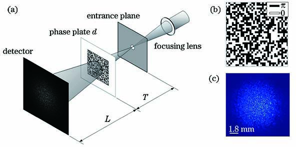
Fig. 1. Basic optical path of CMI algorithm, phase distribution of adopted binary random phase plate, and representative diffraction pattern. (a) Basic optical path of CMI algorithm; (b) phase distribution of adopted binary random phase plate; (c) representative diffraction pattern
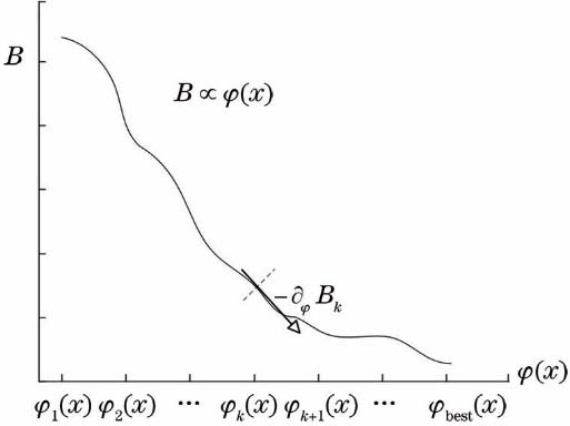
Fig. 2. Relationship between B and φ(x) varying with increasing iterations
Fig. 3. Matrix representation of CMI pattern generation
Fig. 4. Scheme of convolution
Fig. 5. Basic optical path and simulation results. (a) Amplitude and phase of sample; (b) incident light of modulation plate; (c) spectrum and phase map of modulation plate; (d) pattern recorded by detector without modulation plate (image of sample); (e) diffraction pattern with modulation plate; (f) basic optical path
Fig. 6. Reconstructed results with different number of equations. (a) Complete diffraction pattern; (b)--(e) pattern random sampling when Nratio is 0.2, 1, 2, and 5, respectively; (f)--(j) reconstructed results corresponding to Figs. 6(a)--(e)
Fig. 7. Error curve and corresponding error gradient curve under different number of equations
Fig. 8. Reconstructed results under different spectral width of modulation plate. (a)--(e) Spectra of different modulators and corresponding phase maps; (f)--(j) diffraction patterns corresponding to Figs. 8(a)--(e); (k)--(o) reconstructed results corresponding to Figs. 8(a)--(e)
Fig. 9. Error curves and corresponding error gradient curves of reconstructed results with different spectral width of modulation plate
Fig. 10. Reconstruction results of light to be measured with different sparsity characteristics and same spectrum of modulation plate. (a)--(d) Diffraction patterns under different N″; (e)--(h) reconstructed results corresponding to Figs. 10(a)--(d)
Fig. 11. Reconstructed error under different spot width of light to be measured, without modulation plate. Green dashed line represents critical width

Set citation alerts for the article
Please enter your email address
© Copyright 2018-2021 | Chinese Laser Press. All Rights Reserved 沪ICP备15018463号-20