
Dongliang SU, Jin CUI, Pengbo ZHAI, Xiangxin GUO. Mechanism Study on Garnet-type Li6.4La3Zr1.4Ta0.6O12 Regulating the Solid Electrolyte Interphases of Si/C Anodes [J]. Journal of Inorganic Materials, 2022, 37(7): 802
- Journal of Inorganic Materials
- Vol. 37, Issue 7, 802 (2022)
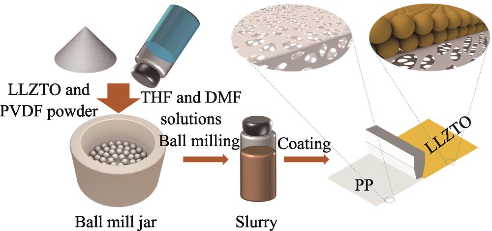
1. Schematic diagram of PP separator coated by LLZTO
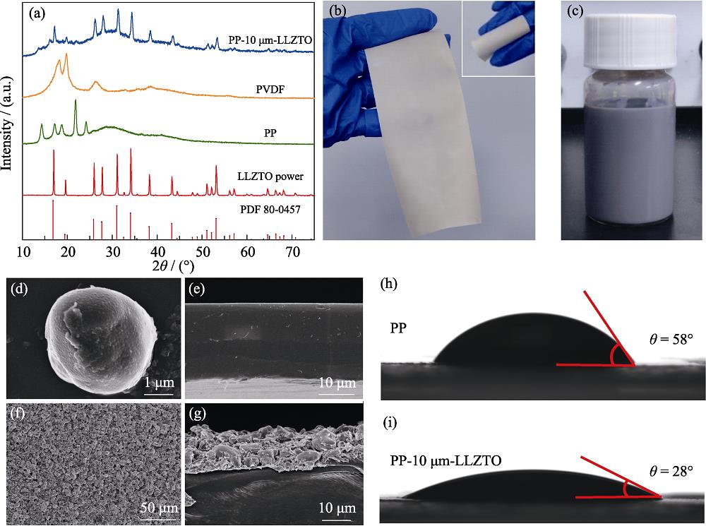
2. Structural characterization of PP-10 μm-LLZTO separator(a) XRD patterns of LLZTO powder, bare PP separator, PVDF and PP-10 μm-LLZTO separator; (b) Optical photos of PP-10 μm-LLZTO separator; (c) Photograph of LLZTO-PVDF slurry after stirring; (d) SEM image of LLZTO powder; (e) Cross-sectional SEM image of PP separator; (f) Top-view and (g) cross-sectional SEM images of PP-10 μm-LLZTO separator; Electrolyte contact angles of (h) PP and (i) PP-10 μm-LLZTO separators
3. Electrochemical performance of Li-Si/C half cells(a) CV curves of the initial 5 cycles of half-cell using PP-10 μm-LLZTO separator; (b) Rate tests of half-cells using PP and PP-10 μm-LLZTO separators; (c) Charge-discharge curves of Li/Si half-cell using PP-10 μm-LLZTO separator; (d) Stability tests of Li/Si half-cells using PP and PP-10 μm-LLZTO separators with different thicknesses; (e) EIS spectra of half-cells with PP and PP-10 μm-LLZTO separators before cycling. Colorful figures are available on website
S1. (a) SEM image and corresponding EDS elemental mapping of Si/C particles, (b) EDS spectrum of Si/C particles
S2. Charge-discharge curves of Li-Si/C half-cell using PP separator
S3. Cross-sectional SEM images of PP-6 μm-LLZTO separator
S4. Cross-sectional SEM images of PP-12 μm-LLZTO separator
S5. Stability test of Li-Si/C half-cell using PP-PVDF separator
S6. (a) Top-view and (b) cross-sectional SEM images of the Si/C anode of the Li|PP-10 μm-LLZTO|Si/C half-cell after 10 cycles
S7. Cross-sectional SEM images of (a) Si/C anode, (b) PP-10 μm-LLZTO separator, (c) Si/C anode, (d) PP-10 μm-LLZTO separator after charge
S8. Equivalent circuit model of bare PP half-cell and PP-10 μm-LLZTO half-cell
S9. (a, c) C1s and (b, d) F1s for SEI of the half-cells with (a, b) PP and (c, d) PP-10 μm-LLZTO separators after 100 cycles
S10. CV curves of initial 3 cycles of the LFP|PP-10 μm-LLZTO|Si/C full cell
S11. (a) Charge-discharge curves during cycling of LFP|PP-10 μm-LLZTO|Si/C at 0.3C; (b) Cycling performances of LFP|PP|Si/C and LFP|PP-10 μm-LLZTO|Si/C at 0.3C
S12. Charge-discharge curves of LFP|PP|Si/C full cell
|
Table 1.
Bulk resistance and ionic conductivity of PP and PP-10 μm-LLZTO separators


Set citation alerts for the article
Please enter your email address

© Copyright 2018-2021 | Chinese Laser Press. All Rights Reserved 沪ICP备15018463号-20