
Dongliang SU, Jin CUI, Pengbo ZHAI, Xiangxin GUO. Mechanism Study on Garnet-type Li6.4La3Zr1.4Ta0.6O12 Regulating the Solid Electrolyte Interphases of Si/C Anodes [J]. Journal of Inorganic Materials, 2022, 37(7): 802
- Journal of Inorganic Materials
- Vol. 37, Issue 7, 802 (2022)
Abstract
Keywords
The rapid development of electric vehicles and portable electronic devices puts forward increasing requirements for the energy density of lithium-ion batteries (LIBs)[1-2]. The low theoretical specific capacity of graphite anodes makes it difficult to meet the demand of improving the energy density of lithium batteries[3-4]. Silicon anode is considered a promising choice for LIBs, benefiting from its ultra-high theoretical specific capacity of 3579 mAh·g-1 referring to Li15Si4, which is 10 times higher than that of graphite[5⇓⇓-8]. Unfortunately, during the charge/discharge process, the large volume change (>300%) leads to the rupture of SEI and pulverization of Si particles, which in turn results in uncontrolled capacity loss[5-6,9].
To overcome the above problems facing the silicon anodes, various approaches have been proposed. First, with respect to design of the nanostructured Si, nanomaterials can reduce the stress caused by volume change, and further improve the cycling stability compared to bulk materials. More recently, Si was designed in different nanostructured to improve cycling stability, e.g., nanoparticles, nanowires, and nanotubes[10]. In this case, the nanostructured Si could tolerate the volume change during the charging/discharging process. Kim, et al.[11] prepared Si nanoparticles (n-Si) with various particle sizes. The initial charge capacity of the 10 nm-sized n-Si was 3380 mAh·g-1, and its capacity dropped to only 81% after 40 cycles. Chan, et al.[12] synthesized the Si nanowires on stainless steel substrates using the Au catalyst. As LIBs anode, Si nanowires achieved the theoretical specific capacity for Si anodes, and the discharge capacity maintained about 75% of this maximum, because they could accommodate large strain without pulverization. Wen, et al.[13] fabricated the Si nanotubes by template method and subsequent a thermal reduction process. Si nanotubes exhibited good rate capability and long- term cycling performance. Second, combining Si particles with the carbon matrix. Although the nanostructure design could alleviate the volume change to a certain extent, the nanostructured Si anodes still exhibited poor electrical conductivity and low lithium-ion diffusivity[14]. To overcome this drawback, a common-used strategy is to incorporate Si with carbon mediums, which possess superior mechanical property, high electron and ion transport rates. In this composite system, silicon materials act as active components contributing to high lithium storage capacity, while carbon matrix significantly buffers volume expansion of Si and improve electronic conductivity of the Si-based anodes. For example, the nanostructured Si/C composite material prepared by Wang, et al.[15] through dispersing nanocrystalline Si in carbon aerogel and subsequent carbonization delivered a capacity of 1450 mAh·g-1 after 50 cycles. Shen, et al.[16] synthesized Si nanoparticles encapsulated into mesoporous carbon sphere via one-step hydrothermal method, which exhibited good cycling stability with a capacity of 581 mAh·g-1 at 0.2 A·g-1 after 100 cycles. Although the electronic conductivity of Si anodes was improved by combining the nanostructured Si with carbon-based materials, the poor stability of the SEI layer still led to the capacity decay of the Si anodes during long-term cycling. Consequently, it remains challenging to regulate the component of SEI to enhance its structural stability and improve the cycling performance of silicon-based lithium batteries.
Herein, to improve the cycling stability of Si/C anodes, we propose a strategy to regulate the SEI composition of Si anodes using Li6.4La3Zr1.4Ta0.6O12 (LLZTO) solid electrolyte. The LLZTO layer was evenly coated on the PP separator by blade coating. Li-Si/C half-cells and LFP-Si/C full cells were constructed, and their electrochemical properties and mechanisms for improving cycling stability were investigated.
1 Experimental
1.1 Preparation of LLZTO powder
The garnet-type Li6.4La3Zr1.4Ta0.6O12 (LLZTO) powders were prepared by the solid-state reaction according to our previous report[17]. Briefly, stoichiometric LiOH·H2O (Aladdin Reagent, 99.95%, 15% excess), La(OH)3 (Aladdin Reagent, 99.95%), ZrO2 (Aladdin Reagent, 99.99%) and Ta2O5 (Aladdin Reagent, 99.95%) were ball-mixed followed by sintering in air under 950 ℃ for 12 h to get the cubic LLZTO powders.
1.2 Preparation of PP-LLZTO
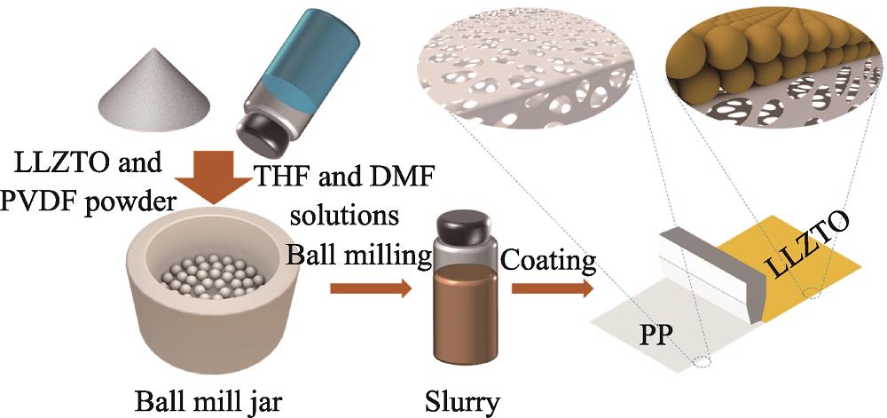
Make the mixed solution of tetrahydrofuran (THF) and dimethylformamide (DMF) in proportions. Certain amount of polyvinylidene fluoride (PVDF) was added to the above solution, and stirred for 2 h to obtain uniformly dispersed PVDF solution. Then, certain amount of LLZTO powder, PVDF solution and LLZTO powder were ball-milled at 200 r/min for 8 h to obtain uniform PVDF-LLZTO slurry. The mass ratio of THF, DMF, PVDF and LLZTO is 13 : 2 : 0.25 : 2.25. The prepared slurry was coated on PP separator to obtain PP-LLZTO separator (Fig. 1). PP-LLZTO separators with different thicknesses of coated LLZTO (i.e. 6, 10 and 12 μm) were prepared by the same method, and named as PP-6 μm- LLZTO, PP-10 μm-LLZTO and PP-12 μm-LLZTO, respectively.
![]()
Figure 1.Schematic diagram of PP separator coated by LLZTO
1.3 Materials characterization
The phase structures were detected by X-ray diffraction (XRD, Bruker D8 discover diffractometer) using Cu Kα1 radiation (λ=0.15406 nm) at step of 0.02°. The surface and cross-sectional morphologies were characterized by Hitachi S-4800 scanning electron microscope (SEM). The X-ray photoelectron spectroscopy (XPS) was performed using a Thermo Fisher Scientific ESCAlab 250 spectrometer, and etching was carried out by Ar ion beam operating at 2 kV and 1 μA for different time.
1.4 Electrochemical measurement and battery assembly
Preparation of Si/C anodes: 5% (in mass) polyacrylic acid (PAA) solution and 2% (in mass) carboxymethyl cellulose (CMC) solution were respectively prepared and mixed. Si/C and acetylene black powders were mixed and ground for 30 min. Then, the ground powders were poured into the mixed solution of PAA and CMC, and stirred for 10 h to obtain the well-dispersed slurry. It was scraped on copper foil and dried in a vacuum drying oven at 80 ℃ for 6 h. The anode electrode sheet was prepared by mixing the Si/C, acetylene black, PAA and CMC in a weight ratio of 12 : 5 : 2 : 1. The active material load is 1.313 mg·cm-2.
Preparation of LFP cathodes: LFP and acetylene black powders were mixed and milled for 15 min. Then, the ground powders were poured into a PVDF solution with a mass fraction of 5% and stirred for 10 h to form well-dispersed slurry. The dispersed slurry was scraped onto aluminum foil and dried in a vacuum drying oven at 60 ℃ for 12 h. The cathode sheet was prepared by mixing LFP, acetylene black, and PVDF in a weight ratio of 8 : 1 : 1. The active substance load is 1.4 mg·cm-2.
Battery assembly: All separators were sandwiched between the lithium sheet and the negative electrode to prepare CR2032 half-cell. 1 mol·L-1 LiPF6 in ethylene carbonate (EC), dimethyl carbonate (DMC), ethyl methyl carbonate (EMC) (1 : 1 : 1 in volume) with 10% fluoroethylene carbonate (FEC) was utilized as electrolyte. The LLZTO side of the PP-LLZTO separators contacted the anode. Each full cell was assembled with a negative electrode sheet and a positive electrode sheet with N/P ratio of 1.26. Cells were assembled in an Ar-filled glove box (Mikrouna) with O2 and H2O contents below 10-7. The cycle and rate performance were tested between 0.01 and 1.5 V using the Neware battery testing system and the LAND battery cycler respectively. The rate performance was measured at 0.1C, 0.3C, 0.5C, 1C, 2C and 4C, respectively. Cyclic voltammetry (CV) was carried out on a Princeton electrochemical workstation at a scan rate of 0.1 mV·s-1. All of the batteries were run at 30 ℃.
2 Results and discussion
Fig. 2(a) shows XRD patterns of bare LLZTO powder, PVDF powder, bare PP and PP-10 μm-LLZTO separators. For PP-10 μm-LLZTO, the peaks at 2θ=14°, 22° can be ascribed to the diffraction peaks of PP, and the others are well indexed to the cubic garnet phase of LLZTO (PDF 80-0457)[18-19]. This indicates that the LLZTO powders are well integrated into the PP separator without losing its crystalline structure. As shown in Fig. 2(b), PP-10 μm- LLZTO exhibits a smooth surface at macro level, which indicates that the LLZTO slurry (Fig. 2(c)) is evenly coated on PP separator. The inset of Fig. 2(b) exhibits excellent flexibility of PP-10 μm-LLZTO separator, and the coated LLZTO does not rupture or fall off under bending. SEM images (Fig. 2(d, e)) show that the average particle size of LLZTO powder is ~300 nm and the thickness of PP separator is ~20 μm. Moreover, a 10 μm-thick layer composed of LLZTO particles is uniformly coated on the surface of PP separator (Fig. 2(f, g)). The electrolyte uptake of the separator plays a critical impact on the ionic conductivity and cycle performance of the LIBs[20]. Generally, the excellent wettability of the separator is helpful for the electrolyte absorption, and further improving the ionic conductivity. The contact angle measurements between the separator and the electrolyte were conducted to characterize the wettability of different separators, and the test results are shown in Fig. 2(h, i). The contact angle between the bare PP separator and the electrolyte is about 58°, while that for PP-10 μm-LLZTO is about 28°. This indicates that the wettability of the PP separator is improved by coating LLZTO layer. Fig. S1(a) shows that the size of primary Si/C particles is ~2 μm and these primary Si/C particles are interconnected to form secondary particles (~20 μm). In addition, energy dispersive X-ray spectroscopy (EDS) analysis demonstrates that Si uniformly disperses in C matrix, whose weight ratio is about 4 : 6 (Fig. S1(b)).
![]()
Figure 2.Structural characterization of PP-10 μm-LLZTO separator(a) XRD patterns of LLZTO powder, bare PP separator, PVDF and PP-10 μm-LLZTO separator; (b) Optical photos of PP-10 μm-LLZTO separator; (c) Photograph of LLZTO-PVDF slurry after stirring; (d) SEM image of LLZTO powder; (e) Cross-sectional SEM image of PP separator; (f) Top-view and (g) cross-sectional SEM images of PP-10 μm-LLZTO separator; Electrolyte contact angles of (h) PP and (i) PP-10 μm-LLZTO separators
![]()
Figure S1.(a) SEM image and corresponding EDS elemental mapping of Si/C particles, (b) EDS spectrum of Si/C particles
Fig. 3(a) shows the initial 5 CV curves of the half-cell with PP-10 μm-LLZTO separator in the potential window of 0.01-1.5 V at a scan rate of 0.1 mV·s-1. The reduction peak at 0.01 V during the first cycle is observed, which is due to the conversion of crystalline silicon to amorphous silicon. In the second cycle, two reduction peaks at 0.01 and 0.15 V correspond to the formation of Li-Si alloy, and two oxidation peak at 0.35 and 0.53 V are assigned to dealloying process of the Li-Si alloy[21⇓-23]. In addition, the rate performances of the half-cells of PP-10 μm-LLZTO and bare PP separators are compared (Fig. 3(b)). Discharge capacities of the half- cell of PP-10 μm-LLZTO are measured as 1410, 1358, 1314, 1221, 949 and 699 mAh·g-1 at 0.1C, 0.3C, 0.5C, 1C, 2C, 4C, respectively. The specific capacity returns to 1390 mAh·g-1 as the current density is reduced to 0.1C, proving the efficient kinetics for lithium storage. For the half-cell with PP separator, when Li+ is transported through the electrolyte in the pores of the separator, it concentrates around the pores, resulting in uneven Li+ transport. This phenomenon is more serious at higher current density. The introduction of LLZTO layer faciletates Li+ transport and reduces Li+ aggregation, thereby improving the rate performance of the battery. In addition, due to the immobilization effect of LLZTO on the anions in the electrolyte, the perturbation of Li+ transport by free ions in the electrolyte is reduced, making Li+ transport more uniform[18]. Fig. S2 and Fig. 3(c) show the charge/discharge profiles of the half-cells with PP and PP-10 μm-LLZTO separators at the 10th, 50th, 100th, and 200th cycle under 0.3C. The voltage polarization of the half-cell using bare PP separator increases signifycantly after 100 cycles, and is much larger than that of the half-cell using PP-10 μm-LLZTO separator.
![]()
Figure 3.Electrochemical performance of Li-Si/C half cells(a) CV curves of the initial 5 cycles of half-cell using PP-10 μm-LLZTO separator; (b) Rate tests of half-cells using PP and PP-10 μm-LLZTO separators; (c) Charge-discharge curves of Li/Si half-cell using PP-10 μm-LLZTO separator; (d) Stability tests of Li/Si half-cells using PP and PP-10 μm-LLZTO separators with different thicknesses; (e) EIS spectra of half-cells with PP and PP-10 μm-LLZTO separators before cycling. Colorful figures are available on website
![]()
Figure S2.Charge-discharge curves of Li-Si/C half-cell using PP separator
To investigate the effect of the coating thicknesses on the cycle performance, the cycling stability of Li-Si/C half-cells with different thicknesses of PP-LLZTO separators were tested. Fig. 3(d) shows the cycling performances of the half-cells using bare PP separator, PP-6 μm-LLZTO, PP-10 μm-LLZTO and PP-12 μm-LLZTO at 0.3C, respectively. The half-cell with bare PP separator exhibits worse stability than those of the PP-LLZTO, because the coated LLZTO layer on the surface of the PP separator can improve the wettability of the electrolyte to the separator (Fig. 2(i)), contributing to a homogeneous Li distribution[18]. Notably, the half-cell using the PP- 10 μm-LLZTO separator exhibits the best cycling stability with the lowest decay rate, the capacity still retains 876 mAh·g-1, corresponding to a capacity retention rate of 81% after 200 cycles at 0.3C (1C=1.5 A·g-1), which can be ascribed to the stable interfacial state of Si anode benefiting from the uniform and complete LLZTO layer of PP-10 μm-LLZTO. In comparison, the poor cycling stability of PP-6 μm-LLZTO results from the thin and uneven coated LLZTO layer (Fig. S3). In addition, relatively thicker LLZTO layer of PP-12 μm-LLZTO leads to the shedding of LLZTO particles and the formation of pores in the layer (Fig. S4), resulting in deteriorated cycling stability. During the initial several cycles, the wetting of LLZTO coating on the surface of PP separator by electrolyte and the formation of SEI on the surface of Si/C electrode causes the fluctuation of battery capacity. In addition, the ambient temperature change can also result in the fluctuation of the cycling curves. To testify the effect of LLZTO on the cycling stability of Li-Si/C half-cells, PP-PVDF separator was prepared by coating LLZTO-free slurry on PP separator. The cycling stability of Li|PP-PVDF|Si/C half-cell was tested. As shown in Fig. S5, Li|PP-PVDF|Si/C half-cell exhibits worse cycling stability than Li|PP|Si/C half-cell. Due to the poor ionic conductivity of PVDF, PVDF layer hinders Li+ transport, which in turn leads to poorer cycling stability. To illustrate the structural integrity and contact between the Si/C anode and the PP-10 μm-LLZTO separator after cycling, SEM characterization of the discharged and charged Li|PP-10 μm-LLZTO|Si/C half-cells after 10 cycles were performed, as shown in Fig. S6(a, b), the Si/C anode maintains good structural integrity, neither pulverization nor falling off from the copper foil. Furthermore, as shown in Fig. S7(a-d), the PP separator is in good contact with the LLZTO layer after charging and discharging, and the Si/C anode particles also maintain close contact. Fig. 3(e) shows the electrochemical impedance spectroscopy (EIS) of the half-cells with bare PP separator and PP-10 μm-LLZTO before cycling. The fitting models and the refined parameters are shown in Fig. S8 and Table S1. It can be found that the introduction of the coating significantly reduces the interfacial resistance of the battery. Specifically, the interfacial resistance (Rf) of the half-cell using the PP-10 μm- LLZTO separator is about 149.1 Ω, which is much smaller than that of the half-cell using bare PP (525.5 Ω). The reduced interfacial impedance indicates the enhanced lithium-ion migration rate in Li/Si half-cell using the PP-10 μm-LLZTO separator, which is beneficial to improve the electrochemical performance of the battery.
![]()
Figure S3.Cross-sectional SEM images of PP-6 μm-LLZTO separator
![]()
Figure S4.Cross-sectional SEM images of PP-12 μm-LLZTO separator
![]()
Figure S5.Stability test of Li-Si/C half-cell using PP-PVDF separator
![]()
Figure S6.(a) Top-view and (b) cross-sectional SEM images of the Si/C anode of the Li|PP-10 μm-LLZTO|Si/C half-cell after 10 cycles
![]()
Figure S7.Cross-sectional SEM images of (a) Si/C anode, (b) PP-10 μm-LLZTO separator, (c) Si/C anode, (d) PP-10 μm-LLZTO separator after charge
![]()
Figure S8.Equivalent circuit model of bare PP half-cell and PP-10 μm-LLZTO half-cell
Table Infomation Is Not EnableTo explain the reason for the improved cycle life of the battery, the SEI composition of Si anodes after cycling was characterized by Ar+-etching-XPS with etching depths of 10, 20, 30, 40 nm, respectively. From the deconvolution of the C1s spectra (Fig. S9(a)), 5 peaks located at around 282.7, 284, 284.8, 286.5, and 289.7 eV are assigned to Li-C, C-C, C-O, CO3-, and C-F, respectively[24⇓-26]. In Fig. S9(c), the content of C-C containing species of Si/C anode in PP-10 μm-LLZTO separator half-cell is lower than that in PP separator, which indicates that SEI of the Si/C anode in PP separator half-cell possesses higher content of organic components. This can be attributed to more severe decomposition reaction of the electrolyte. In F1s spectra (Fig. S9(b)), all peaks are deconvoluted into two typical peaks corresponding to LiF and LiPF6[27]. Since the electrolyte degrades accompanied with the decomposition of the lithium salts, the content of LiF reflects the severity of the electrolyte decomposition. As shown in Fig. S9(d), the SEI-derived LiF content of the Si/C anode with PP separator decreases, further proving that the electrolyte decomposition is more severe in the half-cell using PP separator than PP-10 μm-LLZTO separator. Based on the above analysis, the organic species content of SEI in Si/C anode using PP-10 μm-LLZTO separator is lower than that of Si/C anodes using bare PP separator. The LLZTO coating layer increases the proportion of inorganic components in SEI and enhances the interfacial stability of Si anodes, thereby inhibiting the uncontrollable decomposition of electrolyte.
![]()
Figure S9.(a, c) C1s and (b, d) F1s for SEI of the half-cells with (a, b) PP and (c, d) PP-10 μm-LLZTO separators after 100 cycles
To further demonstrate the superiority of PP-10 μm- LLZTO separator, LFP|PP-10 μm-LLZTO|Si/C and LFP|PP|Si/C full cells were assembled. Fig. S10 depicts the typical CV traces of LFP|PP-10 μm-LLZTO|Si/C full-cell cycled in 2.6-3.8 V at a slow scan rate of 0.1 mV·s-1. The oxidation peak at 3.45 V corresponds to Li-ion extraction from cathode and the combination of Li ions and Si/C anode. The reduction peaks at 3.08 and 3.35 V are ascribed to the removal of Li-ion from the anode and alloying of Li-ion with FePO4[17,28]. LFP|PP- 10 μm-LLZTO|Si/C achieves the excellent cycling performance, and the charge/discharge curves maintain stable during long-term cycling without obvious increment in overpotential (Fig. S11(a)). The capacity still retains 125 mAh·g-1, corresponding to a capacity retention rate of 91.8% after 100 cycles at 0.3C (1C= 170 mA·g-1) (Fig. S11(b)). In contrast, the charge- discharge curves of LFP|PP|Si/C are unstable during the long-term cycling, and the overpotential increases significantly (Fig. S12). Moreover, the capacity of the LFP|PP|Si/ C battery decays rapidly after 25 cycles due to unstable SEI conditions and rapid electrolyte degradation (Fig. S11(b)).
![]()
Figure S10.CV curves of initial 3 cycles of the LFP|PP-10 μm-LLZTO|Si/C full cell
![]()
Figure S11.(a) Charge-discharge curves during cycling of LFP|PP-10 μm-LLZTO|Si/C at 0.3C; (b) Cycling performances of LFP|PP|Si/C and LFP|PP-10 μm-LLZTO|Si/C at 0.3C
![]()
Figure S12.Charge-discharge curves of LFP|PP|Si/C full cell
3 Conclusions
A strategy of regulating the SEI structure by coating Li6.4La3Zr1.4Ta0.6O12 (LLZTO) solid electrolytes onto commercial separator is proposed to improve the electrochemical performances of silicon anodes. The uniform LLZTO layer coated on the surface of PP separator not only improves the wettability of the electrolyte to the separator, thereby homogenizing the lithium-ion flux, but also increases the proportion of inorganic components in SEI, enhancing the interfacial stability of Si/C anodes. As a result, the lithium batteries using the LLZTO-coated PP separator exhibit improved cycling stability and rate capability. Li-Si/C half-cell exhibits a reversible capacity of 876 mAh·g-1 with 81% capacity retention for more than 200 cycles at 0.3C (1C=1.5 A·g-1), and Si/C-LFP full-cell delivers a capacity of 125 mAh·g-1 with 91.8% capacity retention after 100 cycles at 0.3C(1C= 170 mA·g-1). In this work, the structure of SEI on the surface of silicon anodes is regulated by a facile separator modification method, which provides new ideas for construction of high-performance silicon-based lithium batteries.
Supporting materials
Supporting materials related to this article can be found at
References
[2] R B CERVERA, N SUZUKI, T OHNISHI et al. High performance silicon-based anodes in solid-state lithium batteries. Energy & Environmental Science, 662-666(2014).
[18] C Z ZHAO, P Y CHEN, R ZHANG et al. An ion redistributor for dendrite-free lithium metal anodes. Science Advances(2018).
[24] X ZHANG, S WENG, G YANG et al. Interplay between solid-electrolyte interphase and (in) active Li
[27] JIN, B LI Y, K WANG et al. Coordinatively-intertwined dual anionic polysaccharides as binder with 3D network conducive for stable SEI formation in advanced silicon-based anodes. Chemical Engineering Journal(2022).
[28] L LÜ, Y WANG, W HUANG et al. The effect of cathode type on the electrochemical performance of Si-based full cells. Journal of Power Sources(2022).


Set citation alerts for the article
Please enter your email address

© Copyright 2018-2021 | Chinese Laser Press. All Rights Reserved 沪ICP备15018463号-20