A type of scalable self-imaging capable of variable magnification or minification of periodic objects is demonstrated in the focal plane of a lens illuminated by a point source. The theory and the experimental results show that the self-imaging phenomenon can also be realized in the focal plane of a lens regardless of whether the distances satisfy the lens formula or not. The particular property of this scalable self-imaging effect is that the images in the focal plane can be controlled with different scaling factors only when the distances between the point source and the periodic object satisfy a certain condition. This discovery should open a new field of diffraction imaging and new application opportunities in precision measurement.
The self-imaging phenomenon of a periodic object, also known as the Talbot effect, is a fascinating physical effect first discovered by H. F. Talbot in 1836[1]. Since the discovery of this effect, it has been developed in many fields, including plasmonics[2], atom optics[3,4], nonlinear optics[5], exciton-polaritons[6], electronics[7], and transformation optics[8]. The Talbot effect capability of creating an exact replica of a given periodic object has been demonstrated and utilized in many domains, such as array illuminators[9,10], wavefront sensors[11], telecommunication[12–14], lithography[15–17], and array focusing[18]. Moreover, other breakthroughs of the Talbot effect have also been reported in the Airy Talbot effect[19], orbital angular momentum[20], prime number decomposition[21], bidimensional Talbot effect[22], temporal Talbot effect[23,24], angular Talbot effect[25], etc. The conventional Talbot effect (illuminated by a plane wave) principally focuses on the physics phenomenon in free space, i.e., when a periodic object is illuminated by a monochromatic plane wave, the diffraction images of the original object can be reproduced without using a lens. So, this imaging without a lens in free space is also called self-imaging. Exact images with the same period and the structure of the original object can be obtained at specific propagation distances, which are integer multiples of the so-called Talbot distance, while self-images with a period divided by an integer factor can be achieved at a fraction of the Talbot distance[26]. Recently, a bidimensional self-imaging with full independent period control was reported[22]. It is shown that the self-image period along each of the two dimensions can be changed by any desired integer or fractional factor. However, although the period of the original periodic object can be controlled by the fractional Talbot effect or the bidimensional Talbot effect, the size of the periodic object is hard to change. Hence, the self-imaging with a scalable size of the original periodic object is difficult to realize through the conventional Talbot effect in free space. In this Letter, we report that a scalable Talbot effect with a controllable size and period can be realized in the focal plane of a lens. Generally, the exact image of an object cannot be produced in the focal plane of a lens because it does not satisfy the lens formula in geometrical optics. However, through the theoretical analysis and experiment we discover that if a periodic object is illuminated by a suitable point source, the images of the object can be achieved in the focal plane of the lens. Moreover, the images can be controlled with various scaling factors.
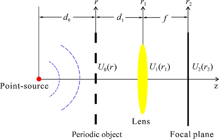
We begin with the theoretical analysis of a periodic object in the focal plane of a lens. As shown in Fig. 1, suppose that a two dimensional (2D) periodic array object is illuminated by a monochromatic diverging spherical wave of unit amplitude. The distribution of the complex field immediately behind the 2D periodic object can be expressed as
Figure 1.Schematic of the scalable Talbot effect in the focal plane of a lens.
For simplicity, we define a quadratic-phase function , where , is the wavelength of the incident beam, and is a parameter describing the distance. In Eq. (1), the diverging spherical wave can be written as in the paraxial approximation, where is the distance of the point source from the periodic object. Note that we entirely neglect the constant term and the finite extent of the object aperture for brevity in this Letter. is the transmittance function of the 2D array object, which can be expressed as the convolution of a lattice function with a complex amplitude of one unit of the periodic array object:where is the symbol for convolution. The lattice function is an array of a 2D periodic delta function determined by the lattice vector , where and are the lattice index and (, ) are the basic vectors of the lattice[27]. Then, using the Fresnel diffraction to account for propagation over a distance , the complex field can be stated as where is the convolution kernel of the Fresnel diffraction, and again the constant term is dropped. After passing through the lens, the transmitted field distribution becomes where is the phase transformation of the lens. Next, after propagating over distance , the distribution of the field at the focal plane of the lens can be expressed as
Sign up for Chinese Optics Letters TOC. Get the latest issue of Chinese Optics Letters delivered right to you!Sign up now
Further, again neglecting a pure phase factor, the focal-plane amplitude distribution can be rewritten as where signifies the Fourier transform operation, and is a quadratic-phase exponential factor. Thus, we see that the complex amplitude distribution in the focal plane of the lens is the Fourier transform of the product of the transmitted field of the object and the diverging spherical wave of the point source. Applying the similarity theorem of the delta function and mathematical manipulation, the Eq. (6) can be further written as where the quadratic-phase exponential factor and is a scaling factor. According to the transfer function approach of the Fresnel diffraction calculation, the diffraction field distribution of Eq. (7) in the focal plane of the lens can be rewritten as where represents the inverse Fourier transform operation and is the Fourier transform of the 2D periodic object, which satisfies the relationship where the coefficient is the area of the unit defined by the basic vector. is the frequency in the frequency spectrum domain. is the reciprocal-lattice vector, where and are the lattice indices and and are the reciprocal basic vectors of the lattice. It is only at the endpoints of the vectors that the values of the reciprocal-lattice function of are not equal to zero. Thus, from Eq. (8), we can see that if the distance of the point source from the object satisfies the condition of where is a positive integer, then the complex amplitude distribution in the focal plane of the lens can be rewritten as
Finally, from Eq. (11), we can see that the complex amplitude distribution of the field in the focal plane of the lens is in proportion to the array object, up to a quadratic-phase exponential factor. Since it is usually the intensity of the image that is interesting, the quadratic phase factor can be omitted. That is an interesting result in the focal plane of a lens. It is known that it is impossible to obtain an exact image of a nonperiodic object in the focal plane of a lens because the object plane and the image plane do not conform to the imaging law of lenses. However, in this Letter, we find that if the object is an array of periodic distribution and illuminated by a point source, scaling images of the periodic object can be achieved in the focal plane of a lens even if the distance does not satisfy the object-image relationship of the lens. Thus, a similar Talbot effect with a scalable size of the original object can be realized as long as the distance satisfies Eq. (10). Consequently, a similar self-imaging phenomenon or Talbot effect can be achieved in the permanent focal plane of the lens, provided the distance of the point source satisfies the condition of Eq. (10). However, the structure of the image in the focal plane of the lens is different from the original array object. The period and the width of the units change with the scaling factor , which is determined by the distance and focal length . Therefore, through changing the distance of the point source from the object or the focal length of the lens, a magnified or minified image can be achieved. In this Letter, we call this type of self-imaging phenomenon the scalable Talbot effect.
Nevertheless, to achieve the scalable Talbot effect in the focal plane of the lens, it is necessary to enable the distance to satisfy the condition of Eq. (10). According to the reciprocal theory of the lattice function[27], the distance from the point source to object can be given by , where is the Talbot distance. It is known that the Talbot distance of a one dimensional (1D) optical grating is , while for a 2D hexagonal array object the Talbot distance is , where is the period of the array object[26,28]. For example, suppose that a 1D grating is illuminated by a point source with the wavelength of . The period of the grating is , and the width of the slits is . Using a fast calculation algorithm of the Fresnel diffraction[29], we can numerically simulate the diffraction patterns of the array object in the focal plane of the lens. Figure 2(a) shows the simulated diffraction images of the grating in the focal plane of a lens. For simplicity, we assume the focal length in the simulation. It is shown that an exact image of the original grating is given when , i.e., the distance , and the scaling factor . Hence, under that condition , the exact Talbot image of the original object can be formed, which is similar to that achieved in the free-space diffraction.
Figure 2.Simulated diffraction patterns in the focal plane. (a) The intensity distribution of the grating with different , and (b) the corresponding curves of the period and slit-width as a function of . Assume the focal length of the lens , where is the Talbot distance, with simulation parameters , . (c) The diffraction images of the grating with different focal lengths , and (d) the corresponding curves of the period and slit-width as a function of the focal length .
From Fig. 2(a), we can see that some similar self-imaging phenomena can also be realized at other distances. When the distance is not equal to the focal length of the lens, the diffraction images are transversally magnified or compressed versions of the original object. The period and slit-width of the images in the focal plane will be changed with various distances of the point source from the object. Since is proportional to the integer , we can see that the period and slit-width of the diffraction images decrease with the increase of . Meanwhile, the images in the focal plane are different from the traditional fractional Talbot image in the Fresnel diffraction with a plane wave. As shown in Fig. 2(a), the slit-width and the period of the grating images are also changed. Figure 2(b) shows the curves of the period and slit-width as a function of . It is shown that the period and slit-width of the diffraction images are inversely proportional to .
These simulated results are consistent with the above theoretical analysis. The scaling factor is inversely proportional to the distance , while it is proportional to the focal length . Figure 2(c) shows the simulated diffraction images of the grating with different . In this simulation, the distance is a constant that equals . Figure 2(d) shows the changing curves of the period and slit-width as a function of the focal length . It is clear to see that the period and slit-width of the diffraction images of the grating have a linear relationship with . It should be noted that this distance between the lens and the periodic object will not affect the self-imaging in the focal plane of the lens. From Eq. (11), we can see that the distance just affects the quadratic-phase exponential factor of . In addition, if the distances of , , and satisfy a particular relationship, this quadratic-phase exponential factor can be canceled. Then this relationship may be helpful in the application of phase measurement.
Figure 3 shows the schematic diagram of the experimental setup. A He–Ne laser (Thorlabs, HRS015B) with wavelength is used. The beam passes through a pinhole (diameter ) spatial filter system (Thorlabs, KT310) to produce a pure point-like light source. The entire pinhole spatial filter system is placed on a motorized linear translation stage (Thorlabs, LTS300), which enables precise tuning of the distance between the point source and the array object (a Cr film on glass fabricated by photoetching). Then, after propagation over a distance behind the array object, the diffraction field is incident on a lens. Thus, the focused field after the lens is recorded by a CCD camera (Daheng Imaging, DH-HV3151UC) with the pixel size of . This experimental setup allows us to record the diffraction patterns of the array object in the focal plane of the lens. The array object is a 1D grating with a period of and a slit-width of . So, the Talbot distance is .
Figure 3.Schematic diagram of the experimental setup.
Figure 4 shows the experimental results with various distances and the focal lengths of the lens. Figure 4(a) shows the patterns recorded through the CCD camera with the distance changed from up to , confirming the observation of the predicted scalable self-imaging effects of the diffracted waves in the focal plane of the lens. Figure 4(b) shows the experimental results with the various focal lengths of the lens when the distance between the point source and the 1D grating is a constant of . We can see that the slit-width and the period of the grating images are also changed with the various focal lengths .
Figure 4.Experimental results recorded by the CCD with (a) various distances when the focal length and (b) various focal lengths when the distance .
Figures 5(a) and 5(b) show the corresponding 1D curves of the centerlines shown in Figure 4. Figures 5(c) and 5(d) show the changing curves of the period and slit-width as a function of and the focal length . It is clear to see that the period and the slit-width of the diffraction images of the grating are inversely proportional to while they are proportional to , which is entirely consistent with the theoretical prediction. That is to say, a magnified image can be achieved when the scaling factor , while a minified image can be obtained when the scaling factor . Therefore, through changing the scaling factor , i.e., changing or , the scalable Talbot effect can be realized in the focal plane of a lens.
Figure 5.(a) and (b) are the corresponding 1D curves of the centerlines shown in Figure 4. (c) and (d) are the period and slit-width as a function of the distance parameter and the focal length .
In addition, the scalable Talbot effect for other 2D array objects can also be achieved. Figure 6 shows the experimental results of a hexagonal array object with period , and the focal length of the lens used in the experiment is 300 mm. Figure 6(a) shows the image recorded by the CCD when the distance , while Fig. 6(b) shows the recorded image when . It is shown that the period and the size of the hexagon are reduced by half when the distance changed from to . These results confirm that the scalable images of various array objects can be produced in the focal plane of a lens, regardless of whether the lens law is satisfied, in agreement with our theoretical predictions. Also, as predicted, when satisfies the condition of Eq. (10), the scaling self-imaging of the array object can be achieved.
Figure 6.Experimental results recorded by the CCD with a hexagonal array object with period and the focal length of the lens is 300 mm. (a) , (b) .
In summary, we have demonstrated a scalable Talbot effect in the focal plane of a lens. The first theoretical prediction and experimental observation of scaling self-imaging effects are given. Some scaling images with various magnified or minified factors can be realized when the periodic array objects are illuminated by a suitable spherical wavefront. This kind of self-imaging phenomenon in the focal plane of a lens should open the path for novel physics phenomena and new applications in the field of imaging and measurement. It should be noted that the scalable Talbot effect can also be achieved when is a fraction. However, this scalable Talbot effect with fraction is different from the conventional fractional Talbot effect, which will be discussed in future research. Moreover, the new optical illuminating source[30,31] can be utilized to enhance the optical imaging efficiency and resolution in the application.
[6] T. Gao, E. Estrecho, G. Li, O. A. Egorov, X. Ma, K. Winkler, M. Kamp, C. Schneider, S. Hofling, A. G. Truscott, E. A. Ostrovskaya. Phys. Rev. Lett., 117, 7(2016).