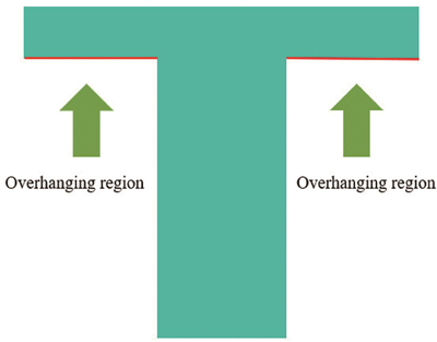
Fig. 1. Schematic diagram of the overhanging structure, where the red areas is the overhanging structure areas
Fig. 2. SLM printing at seven different overhang angles
[21] Fig. 3. Schematic diagram of self-supporting. The orange area represents the print layer, and the green areas represent the finish print layers. When the orange area can be printed, the structure is considered to be self-supporting
Fig. 4. Definition of supporting region
for element
[30] Fig. 5. Definition of 3D AM filter, where the blue region
denotes the supporting region of an element at position
in a mesh
[31] Fig. 6. Flowchart of the topology optimization process with overhang constraint
[37] (After selecting the appropriate reference domain, define the underlying data for the structural analysis. Then, the optimization loop is performed, which includes defining the topology optimization parameters, obtaining the physical density field, profile evaluation, finite element method calculations, and sensitivity analysis)
Fig. 7. Two-dimensional test results of MBB and cantilever beams. (a) MBB beams obtained by Langelaar
[30]; (b) MBB beams obtained by Garaigordobil
et al.[37]; (c)–(f) optimal topology structures with different critical angles of 45°, 60°, 80°, and 90° obtained by Garaigordobil
et al.[37] Fig. 8. Smooth topology structure and density of grid points within elements
[40] ( Divide the element points into
N grid points. When
, grid points are solid points; when
, the grid point is a void point)
Fig. 9. Cubic univariate B-spline basis functions with uniform and open knot vectors
[42] Fig. 10. Optimal structural configuration of the cantilever beam without constraints
[45] Fig. 11. Graph of convergence history and calculation time of the cantilever beam re-optimization step
[45] Fig. 12. Structural skeleton deposition path under level set and overhang constraint modeling based on multi-layer level set
[47]. (a)‒(b) Two examples of a horizontal set-based deposition path; (c) modeling of overhang constraint base on multi-layer level set, where
d represents the maximum overhang length constraint and the critical overhang angle is set to 45°
Fig. 13. Downward cusp
[48] Fig. 14. Skeleton segmentation
[49]. (a) Structural topology; (b) identified skeleton; (c) identified intersection and end points; (d) segmented structural skeletons; (e) segmented structural areas
Fig. 15. Threshold self-supporting conditions
[49]. (a) Threshold self-supporting condition when the building direction aligns with the
y-axis; (b) threshold self-supporting condition when the building direction deviates from the
y-axis
Fig. 16. Overhang recognition
[52]. (a) Five yellow elements in the supporting region can support the target element; (b) the target element can support five green elements in the supported region
Fig. 17. Optimization results of the self-supporting cantilever beams. (a) Self-supporting cantilever beam proposed by Bi
et al.[52]; (b) self-supporting cantilever beam proposed by Langelaar
[31] Fig. 18. Basic idea of the MMC-based and MMV-based topology optimization approaches
[53]. (a) Topology optimization evolution process based on MMC; (b) topology optimization evolution process based on MMV
Fig. 19. Definition of polygons with odd and even sides
[54]. (a) An 11-side polygon; (b) a 12-side polygon
Fig. 20. Illustration of proposed approach for self-supporting design of cantilever beam proposed based on solid polygon features
[55] Fig. 21. Three-dimensional cantilever beam with virtual skeleton
[56] Fig. 22. Hemp cantilever: comparison of solutions obtained through layout optimization and continuous topology optimization
[57] Fig. 23. Test results of the structural layout, geometric optimization and 3D printing of the bidirectional center-stressed vertical truss considering different self-supporting critical angles
[22] Fig. 24. A direction-driven shape optimization program that significantly reduces the use of support materials
[58]. (a) Initial design; (b) adjusted new scheme, with the support structure indicated in blue
Fig. 25. Filling optimization process using a rhombic structure: by performing a so-called carving operation on each leaf node of the rhombic tree, the rhombic element is converted into a rhombic shell with a given wall thickness
[61] Fig. 26. Flow diagram of the self-supporting hollow filling structure algorithm
[62]. (a) A triangular mesh is first entered, and the self-supporting infill structure is generated in its offset version; (b) randomly generate a large number of inner pillars and nodes, and initialize the radius of all pillars; (c) elimination of all redundant struts and non-self-supporting struts; (d) further optimization of inner pillars and joints to reduce material usage; (e) the model is generated by three forces: one at the top and the other two on the sides
Fig. 27. Microscopic infill structures. (a) Multi-faceted Voronoi structure
[63]; (b) CrossFill-filled structure similar to foam
[64] Fig. 28. Unit cells of the layer-based infill structure are reconstructed by cross-sections, where
pi represents the starting point, the blue polygon is the hexagonal cross-section, the red and green polygons are two equilateral triangular cross-sections, and the orange and purple polygons are two adjacent cross-sections
[65] Fig. 29. Printing effect of a kitten model. (a) A porous structure similar to a skeleton
[66]; (b) elliptical hollow structure
[67] Fig. 30. Filling structural elements based on layers and the printed result
[68]. (a) Filling elements; (b) print result
Fig. 31. Overhang constraints based on AM filter
[69] Fig. 32. Improved parametrization scheme based on the two fields formulation (green: the objective function; blue: global volume constraint; red: local volume constraint; brown: overhang constraint)
[70] Fig. 33. Sensitivity parallel solving flowchart
[71] Fig. 34. Optimization effect of MBB beam
[73]. (a) Unconstrained; (b) overhang angle constraints; (c) overhang angle and height constraints
Fig. 35. Optimized MBB beam results under self-support constraint, considering the printing direction and the overhang angle: the change of the substrate represents different printing directions
[74] Fig. 36. Printing of beam parts
[75]. (a) Original model; (b) printed model
Fig. 37. Simulation results of residual stress distribution of MBB beam
[77]. (a) Self-supporting but without residual stress constraints; (b) self-supporting and residual stress constraints
Method | Advantages | Limitations |
---|
Based on SIMP method | (1)The optimization algorithm converges well and the sensitivity is simple and easy to calculate (2)Discrete design sensitivity calculations based on finite elements can be performed directly (3)Suitable for combining more complex nonlinear structural topologies,such as geometric and material nonlinear problems | (1)Numerical instability (2)Existence of intermediate densities (3)Prone to local minima | Based on the level set method | (1)Simple principles and clear boundaries (2)No numerical instability (3)No intermediate density | (1)Geometry is limited by existing boundaries (2)Weak convergence (3)Presence of initial dependencies | Based on bi-directional evolutionary structural optimization | (1)Practical principles,simple algorithms (2)Grid-independent (3)Easy to generate good solutions | (1)The more iterations there are,the less efficient the computation becomes (2)Instability of existing values (3)The optimization scheme depends on the type and size of the mesh | Based on feature-driven approach | (1)Co-design and topology optimization of features (2)Few design variables,computationally efficient,clear boundaries (3)Easy and seamless integration with mainstream CAD | (1)Stronger dependence on the number of features and layout (2)Presence of unsmooth boundaries |
|
Table 1. Advantages and disadvantages of structural self-supporting design methods based on continuum structure topology optimization
Ref. | Author | Printing platform | Advantages | Limitations |
---|
[30-31] | Matthijs Langelaar | Selective laser melting(SLM) | (1)Overcomes non-printability and related inefficiencies (2)Process simulations can be performed to strictly consider overhang constraints and ensure self-support at each layer (3)Extended to 3D design | (1)Rectangular grid only (2)Limited to specified critical overhang angle | [34] | Martin Leary, et al. | Fused deposition modeling(FDM) | (1)Collapse of large overhanging areas is avoided | (1)Not fully self-supporting printing | [37] | Alain Garaigordobil, et al. | | (1)Precise detection of contours (2)Any critical overhang angle can be specified (3)The proposed constraints are easy to add to a topology optimization program and easy to incorporate with any generic optimizer | (1)Not extended to 3D design | [38] | Yu Hsin Kuo, et al. | FDM | (1)The self-supporting index is continuous and can be directly differentiated for sensitivity analysis (2)Easily adapted to different overhang angles or self-supporting design domains | (1)Imposed length constraints are not considered | [40-41] | Yun-Fei Fu,et al. | FDM/SLM | (1)The jagged and fuzzy boundary problems caused by the traditional SIMP method can be solved (2)Lower compliance can be obtained | (1)AM-oriented topology optimization requires more material to form a complete self-supporting structure when the structure volume fraction is relatively small | [42] | Wang Che, et al. | | (1)The number of design variables is substantially reduced,allowing easy and accurate calculation of density gradients (2)Overhang constraints are independent of the finite element mesh and are suitable for design domains with irregular boundary shapes | (1)Not extended to 3D design (2)The optimization results are highly dependent on the print direction and critical overhang angle | [44] | Wu Zijun, et al. | | (1)Combined overhang angle,overhang length,and print orientation (2)Integration of structural design and manufacturing | (1)Computational efficiency needs to be improved (2)Stress constraints are not considered | [45] | Ye Jun, et al. | | (1)Low loss of structural performance | (1)Not extended to 3D design |
|
Table 2. Advantages and disadvantages of self-supporting design based on SIMP
Ref. | Author | Printing platform | Achievement or advantages |
---|
[47] | Liu Jikai, et al. | FDM | (1)Proposing a structural skeleton based on deposition path planning to solve the material anisotropy problem (2)Proposing a multi-story horizontal set frame incorporating overhang length to solve the structural self-support problem | [48] | Wang Yaguang, et al. | | (1)The overhang constraint is expressed as a domain integral of the gradient of the level set function,which helps to detect violations of the overhang angle (2)Can handle any initial design and overhang angle (3)Optimized design meets overhang constraints without much loss of stiffness | [49] | Liu Jikai, et al. | FDM | (1)Proposing new threshold conditions that synthesize overhang dimensions and inclination angles (2)The proposed method is applicable to a wide range of additive manufacturing equipment |
|
Table 3. Achievements of some researchers on structural self-supporting design based on level set and the advantages of the proposed methods
Ref. | Author | Advantages | Disadvantages |
---|
[53] | Guo Xu, et al. | (1)Some of the inherent difficulties associated with stress-constrained topology optimization(e.g.,locally stress-constrained singularities,accuracy of stress calculations)can be directly eliminated (2)A direct link can be established between the optimization results and the CAE system (3)Improve accuracy of stress calculations along structural boundaries (4)Greatly reduces the computational effort of finite element analysis | (1)A smooth transition of the boundary contour around the intersecting portion of the component is not achieved to mitigate stress concentrations | [54] | Zhang Weihong, et al. | (1)Eliminate V- area not printable problem (2)Easily scalable to 3D cases | (1)Reduces the performance of the structure | [55] | Zhou Lu, et al. | (1)Precise overhang angle control is available (2)Small overhang angles can be printed (3)Fine topology with more features can be designed | (1)Reduced structural stiffness |
|
Table 4. Advantages and disadvantages of feature-driven optimization methods
Ref. | Author | Details | Advantages |
---|
[61] | Wu Jun, et al. | A filling structure based on the generation of self-support on rhombic cells is proposed | (1)Boundaries that ensure optimized maximum overhang angles and minimum wall thicknesses for internal structures (2)Good mechanical stiffness and static stability | [62] | Wang Weiming, et al. | A sparsity optimization method is proposed to eliminate redundant and unsupported struts,and overhang angle optimization is proposed to achieve unsupported design | (1)More material saving | [63] | Jonàs Martínez, et al. | A microstructure based on Voronoi diagrams is proposed which strictly enforces the three constraint requirements of continuity,self-support and overhang angle | (1)Good elastic properties | [64] | Tim Kuipers, et al. | A foamy CrossFill structure with a single,continuous,non-overlapping layer in each layer is proposed to realize self-supporting of the filled structure | (1)The structure is more supple and suitable for the application of objects such as shoes | [65] | Xu Wenpeng, et al. | A novel lightweight infill structure based on a layer structure whose layers are continuously and periodically transformed between triangles and hexagons is presented | (1)No additional slicing process is required,reducing time-consumption (2)The proposed structure has comparable structural performance under different loading conditions | [66] | Wu Jun, et al. | A method for filling bone-like porous structures based on the voxel topology optimization method is proposed | (1)Good mechanical properties (2)Good resistance to damage | [67] | Mokwon Lee,et al. | An elliptic Voronoi filling structure based on greedy algorithm is proposed | (1)Compared to Ref.[61],the problem of stress concentration is avoided | [68] | Xu Wenpeng, et al. | A layer-based infill structure is proposed to realize the self-supporting and connectivity of the infill structure by adjusting the parameters to control the continuous periodic changes of the ortho-triangles of different layers | (1)Good spatial connectivity | [69] | Liu Yichang, et al. | An infill structure design method that introduces overhang constraints and minimum length scale constraints and is based on the density method is proposed,and self-supporting of infill structures has been realized | (1)More design freedom (2)Exhibits better mechanical properties compared to predefined periodic fill patterns | [70] | Zhou Mingdong, et al. | A self-supporting infill structure design method based on the density method is proposed,where overhang constraints are introduced to ensure accurate control of overhangs and dual-field parameters are introduced to control the minimum length scale | (1)Full self-support of the structure in the actual print can be ensured |
|
Table 5. Comparison of the contents and advantages of the self-supporting design of the filling structure