• Journal of Infrared and Millimeter Waves
  • Vol. 40, Issue 4, 496 (2021)
Ye ZHANG, Xiao YANG, Xin-Rui JIANG, Qi YANG, Bin DENG*, and Hong-Qiang WANG
Author Affiliations
  • College of Electronic Science and Technology, National University of Defense Technology, Changsha 410073, China
  • show less
    DOI: 10.11972/j.issn.1001-9014.2021.04.009 Cite this Article
    Ye ZHANG, Xiao YANG, Xin-Rui JIANG, Qi YANG, Bin DENG, Hong-Qiang WANG. Attitude direction estimation of space target parabolic antenna loads using sequential terahertz ISAR images[J]. Journal of Infrared and Millimeter Waves, 2021, 40(4): 496 Copy Citation Text show less
    Space target observation geometry of space-based terahertz radar.
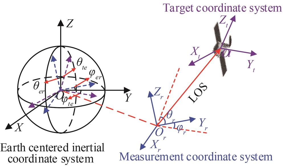
    Fig. 1. Space target observation geometry of space-based terahertz radar.
    Geometry model of a paraboloid.
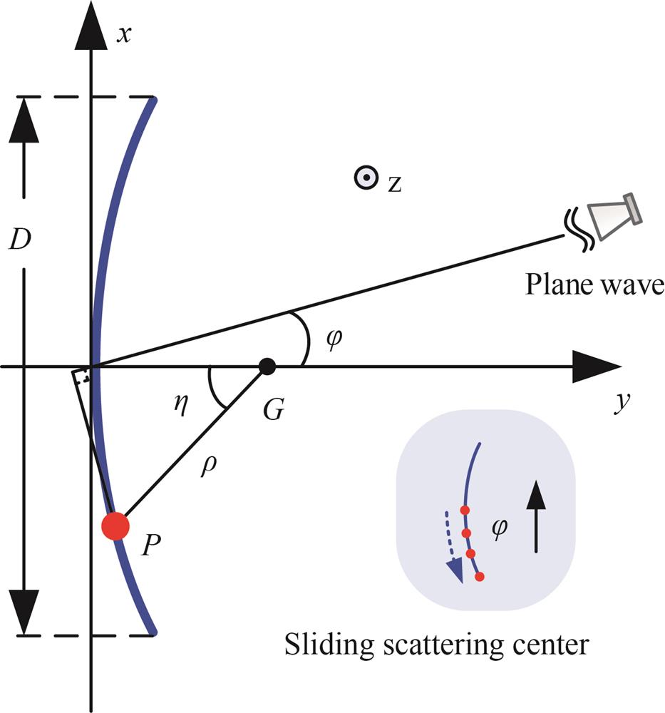
    Fig. 2. Geometry model of a paraboloid.
    RCS of the parabolic antenna model at 0.22 THz.
    Fig. 3. RCS of the parabolic antenna model at 0.22 THz.
    ISAR images of the parabolic antenna model(a) φ=25°, VV polarization; (b) φ=60°, VV polarization; (c) φ=60°, VH polarization
    Fig. 4. ISAR images of the parabolic antenna model(a) φ=25°, VV polarization; (b) φ=60°, VV polarization; (c) φ=60°, VH polarization
    Flowchart of the attitude direction estimation process
    Fig. 5. Flowchart of the attitude direction estimation process
    Equivalent observation scene of ISAR imaging
    Fig. 6. Equivalent observation scene of ISAR imaging
    ISAR imaging results of the parabolic antenna model(a) Ku-band radar,(b) terahertz radar
    Fig. 7. ISAR imaging results of the parabolic antenna model(a) Ku-band radar,(b) terahertz radar
    Simplified three-dimensional satellite model
    Fig. 8. Simplified three-dimensional satellite model
    Radar tracking LOS angle trajectory
    Fig. 9. Radar tracking LOS angle trajectory
    Sequential terahertz ISAR imaging results
    Fig. 10. Sequential terahertz ISAR imaging results
    Solar panel component detection results (marked with blue solid lines)
    Fig. 11. Solar panel component detection results (marked with blue solid lines)
    Parabolic antenna component detection results (marked with blue solid lines)
    Fig. 12. Parabolic antenna component detection results (marked with blue solid lines)
    Absolute error of estimated ellipse parameters in each ISAR image
    Fig. 13. Absolute error of estimated ellipse parameters in each ISAR image
    Absolute error of attitude direction parameters
    Fig. 14. Absolute error of attitude direction parameters
    Radar typeKu-band radarterahertz radar
    Center frequency of signal16.7 GHz220 GHz
    Bandwidth2 GHz10 GHz
    Range resolution7.5 cm1.5 cm
    Table 1. Main Parameters of the ISAR System
    Parameter typeTrue valueEstimated valueAbsolute error
    Center coordinates(-1 m,-0.1 m,0.2 m)(-0.996 5 m,-0.103 1 m,0.187 3 m)(0.003 5 m,0.003 1 m,0.012 7 m)
    Length of radius0.25 m0.246 5 m0.003 5 m
    Attitude direction(50°,220°)(50.913 5°,221.172 6°)(0.913 5°,1.172 6°)
    Table 2. Estimation Results of Parabolic Antenna Parameters
    Ye ZHANG, Xiao YANG, Xin-Rui JIANG, Qi YANG, Bin DENG, Hong-Qiang WANG. Attitude direction estimation of space target parabolic antenna loads using sequential terahertz ISAR images[J]. Journal of Infrared and Millimeter Waves, 2021, 40(4): 496
    Download Citation