• Infrared and Laser Engineering
  • Vol. 50, Issue 12, 20210172 (2021)
Xiangyu Li1、2, Bo Peng1、2, Bo Jiang1, and Ping Ruan1
Author Affiliations
  • 1Xi'an Institute of Optics and Precision Mechanics, Chinese Academy of Sciences, Xi'an 710119, China
  • 2University of Chinese Academy of Sciences, Beijing 100049, China
  • show less
    DOI: 10.3788/IRLA20210172 Cite this Article
    Xiangyu Li, Bo Peng, Bo Jiang, Ping Ruan. Tilt error correction of minitype theodolite’s vertical shaft based on angular contact ball bearings[J]. Infrared and Laser Engineering, 2021, 50(12): 20210172 Copy Citation Text show less
    Vertical shaft based on angular contact ball bearings
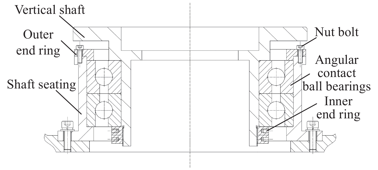
    Fig. 1. Vertical shaft based on angular contact ball bearings
    Gap design of vertical shaft
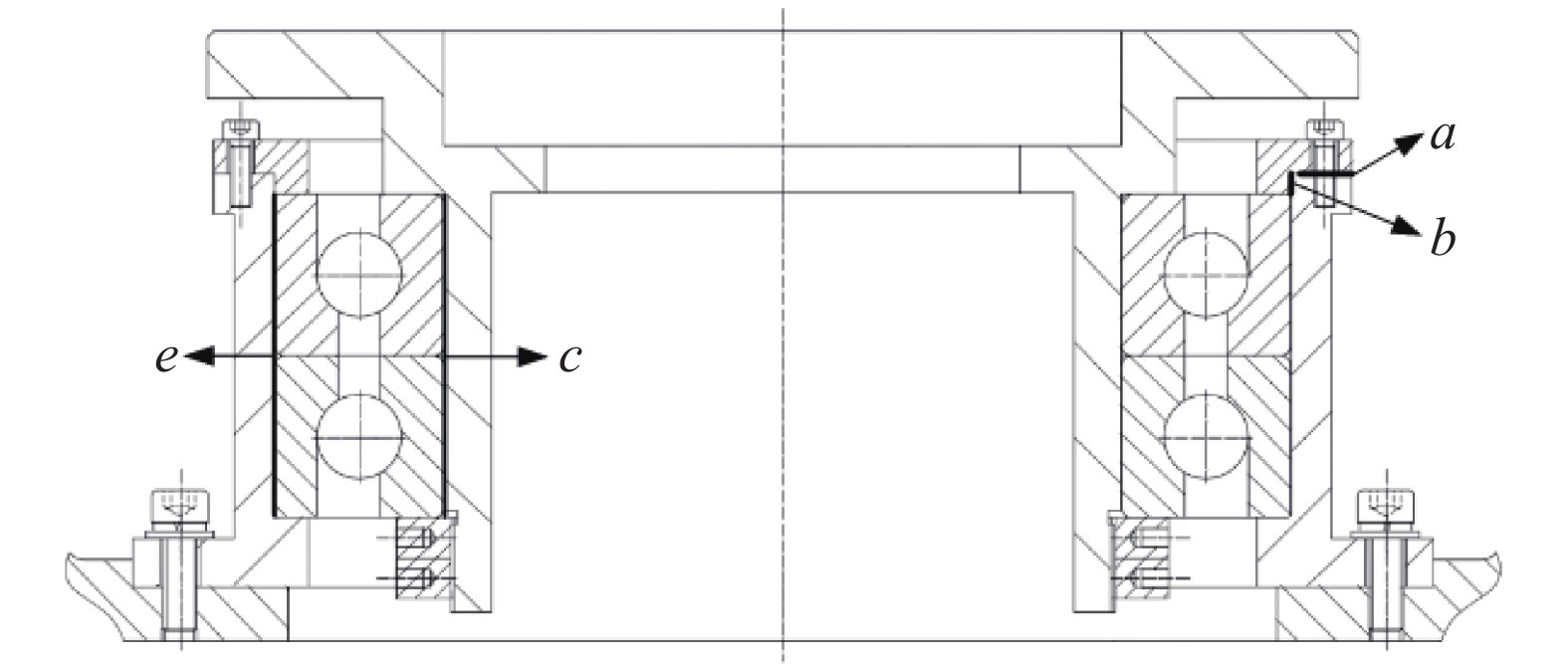
    Fig. 2. Gap design of vertical shaft
    Theoretical pressing force model of single nut bolt
    Fig. 3. Theoretical pressing force model of single nut bolt
    Pressing model of bearing outer ring
    Fig. 4. Pressing model of bearing outer ring
    Boundary conditions and nut bolts' pressing force
    Fig. 5. Boundary conditions and nut bolts' pressing force
    Pressing force of bearing outer ring 轴承外圈压紧力
    Fig. 6. Pressing force of bearing outer ring 轴承外圈压紧力
    Deformed cloud diagram of outer end ring
    Fig. 7. Deformed cloud diagram of outer end ring
    Deformed cloud diagram of outer end ring (×10)
    Fig. 8. Deformed cloud diagram of outer end ring (×10)
    Deformed cloud diagram of bearing outer ring I
    Fig. 9. Deformed cloud diagram of bearing outer ring I
    Design optimization flow
    Fig. 10. Design optimization flow
    Relation between 关系曲线图
    Fig. 11. Relation between 关系曲线图
    Relation between 关系曲线图
    Fig. 12. Relation between 关系曲线图
    Relation between 关系曲线图
    Fig. 13. Relation between 关系曲线图
    Initial state of rotation center axis
    Fig. 14. Initial state of rotation center axis
    State of shafting after instability
    Fig. 15. State of shafting after instability
    Three contact conditions under ideal conditions
    Fig. 16. Three contact conditions under ideal conditions
    Displacement monitoring of shaft with partial load
    Fig. 17. Displacement monitoring of shaft with partial load
    Elimination of bearing clearance under Condition II
    Fig. 18. Elimination of bearing clearance under Condition II
    Hoisting under partial load
    Fig. 19. Hoisting under partial load
    Radial clearance /mm These load/kNPre-load /N Axial runout /mm Radial runout /mm
    StaticDynamic
    −0.01- −0.0031541225400.0060.006
    Table 1. Parameters of bearing
    Elastic modulus /GPa Ratio of poisson, μDensity /kg·m−3
    680.332770
    Table 2. Material parameters of 2A12/T4
    Elastic modulus /GPa Ratio of poisson, μDensity /kg·m−3
    2090.2697890
    Table 3. Material parameters of 45
    Elastic modulus /GPa Ratio of poisson, μDensity /kg·m−3
    2190.37830
    Table 4. Material parameters of GCr15
    Condition ICondition IICondition III
    LoadUnloadLoadUnloadLoadUnload
    0.050.0250.02500.030.002
    Table 5. Displacement of monitoring points with different conditions (Unit: mm)
    Condition ICondition IICondition III
    Test 1Test 2Test 1Test 2Test 1Test 2
    −19−20.5+2.7+1.9+4.8+6.1
    Table 6. Biaxial perpendicularity error(Unit: (″))
    Xiangyu Li, Bo Peng, Bo Jiang, Ping Ruan. Tilt error correction of minitype theodolite’s vertical shaft based on angular contact ball bearings[J]. Infrared and Laser Engineering, 2021, 50(12): 20210172
    Download Citation