
Shuaiyu Zhang, Guohang Hu, Lin Wang, Yongjiang Liu, Ling Wei, Yifan Zheng, Yuchuan Shao. [J]. Laser & Optoelectronics Progress, 2022, 59(17): 1736001
- Laser & Optoelectronics Progress
- Vol. 59, Issue 17, 1736001 (2022)
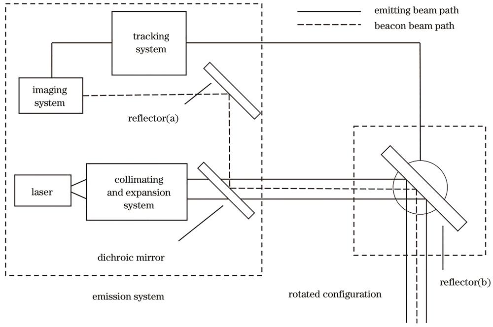
Fig. 1. Schematic system part of the experimental setup
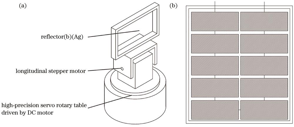
Fig. 2. Schematic. (a) Structure of high-precision servo rotary table; (b) schematic of the photovoltaic cell
Fig. 3. Experimental results. (a) Schematic system part of the experimental setup; (b) initial position information collected by an imaging system (square represents the view field range); (c) new position information when the system is tracking; (d) image of the view field when PV moves to the left; (e) image of the view field when PV moves to the right
Fig. 4. Missing distance under dynamic condition at different speeds. (a) 0 mm/s; (b) 50 mm/s; (c) 100 mm/s; (d) 200 mm/s
Fig. 5. Dynamic output characteristic curves of PV under different transverse speeds with different powers of laser irradiation. (a) 12.7 W; (b) 25.4 W
Fig. 6. Images of tracking the missing distance for different flight conditions. (a) Hovering flight; (b) (c) horizontal flight; (d) missing distance dependence on time
|
Table 0. Detailed parameters of high-precision servo rotary table driven by a DC and longitudinal stepper motor
|
Table 0. Efficiency loss under different conditions

Set citation alerts for the article
Please enter your email address
© Copyright 2018-2021 | Chinese Laser Press. All Rights Reserved 沪ICP备15018463号-20