We design a novel wireless laser power transmission system in which the process of wireless power transmission to a dynamic target was completed based on the rotation of just one component. The design of this system not only reduces the load-bearing of the gimbal, but also avoids the degradation of beam quality caused by lens vibration when tracking dynamic targets. As a result, this WLPT system has been verified by tracking an unmanned aerial vehicle at 122 m away with an offset distance of ±26.7 mm. We believe this system offers great potential in high-power, long-distance dynamic laser power transmission.We design a novel wireless laser power transmission system in which the process of wireless power transmission to a dynamic target was completed based on the rotation of just one component. The design of this system not only reduces the load-bearing of the gimbal, but also avoids the degradation of beam quality caused by lens vibration when tracking dynamic targets. As a result, this WLPT system has been verified by tracking an unmanned aerial vehicle at 122 m away with an offset distance of ±26.7 mm. We believe this system offers great potential in high-power, long-distance dynamic laser power transmission.
1 Introduction
Wireless laser power transmission (WLPT) is a technology that uses laser beams for long-distance energy transfer. It is an effective way to solve conventional cable power supply problems[1-4]. Although proposed early, only recently has it been confirmed successively[5-6]. In 2003, National Aeronautics and Space Administration(NASA) manually powered a small aircraft to sustain a flight at 15 m for 15 min irradiated using a laser of 500 W[7]. In 2007, Kinki University in Japan used a laser with a power of 300 W to deliver energy to an electric kite. They sustained an hour flight at an altitude of 50 m with an autotracking system[8]. In 2012, Lockheed Martin and laser motive powered a stalker unmanned aerial vehicle (UAV) by irradiating photovoltaic cells with lasers and increased its flight time from 2 h to more than 48 h[9]. Until now, highly efficient photovoltaics (PVs) have been the primary energy receiving devices in WLPT systems[10-14]. Hence, the tracking accuracy of the system can be directly presented as the variation in PVs’ output characteristics.
Presently, the structure of conventional WLPT systems can be summarized as: the laser fiber is connected to an “emitting cylinder”, including a series of lens sets, such as collimation and beam expanding systems. Next, a beacon light source is placed on the emitting cylinder, providing position information of the target to the imaging system. This emitting cylinder, with many components, is mounted on a gimbal. The central location of the PV is captured and processed by the computer in the form of optical signals. The azimuth of the emitting cylinder is controlled to aim at the center of the PV for laser irradiation using the position information[5-9].
The ability of the emitting cylinder to rotate at 360° is the major advantage of the conventional WLPT with the above-mentioned structure. However, it is impractical for the dynamic target to fly at a wide-angle for long-distance energy transmission since the target flies around a specified position instead of the system. Multiple rotations may lead to the winding of fibers, thus, causing cumulative damage to the inside optical structure. Furthermore, better beam quality means more lens sets are placed on the gimbal along with the emitting cylinder. The gimbal will inevitably vibrate when tracking at high speed, resulting in a worse performance of lens sets than the static irradiation condition. For the limited gimbal area, the subsequent expansion and optimization design for different transmission powers and distances are challenging to achieve once the optical path structure is determined.
Here, we proposed a dynamic laser wireless energy transfer system using a single rotation device. First, the emitting cylinder was split into an emitting system and a rotate configuration for laser power supply and azimuth control, respectively. Compared with the previous system, our proposed system has the following advantages: 1) the emission components, including laser and lens sets are placed on a stationary platform, thereby preventing mechanical vibrations caused by rotation. 2) The azimuth of the beam is controlled only by a reflector mounted on the rotation device, which guarantees the tracking accuracy of the system. 3) For different scenarios, the optical path of this system can be optimized as wished. Therefore, we have verified the accuracy tracking capability of the system by performing a low corresponding loss of transmission efficiencies of 0%, 0.02%, and 0.08% with 12.7 W output, and 0%, 0.03%, and 0.05% with 25.4 W output, respectively.
2 Experimental Setup
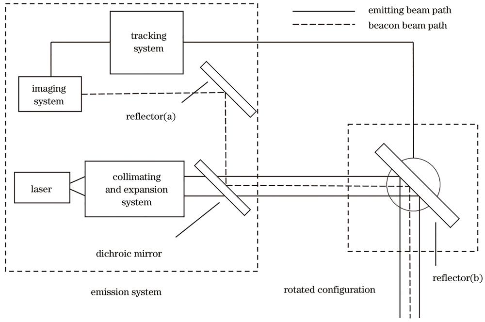
Fig. 1 illustrates the proposed system, which can be separated into two parts: emission system and rotation configuration. The emission system consists of a laser, collimating and expansion system, tracking system, dichroic mirror, imaging system, and reflector (a), used for receiving the beacon beam to obtain the dynamic target position. Only reflector (b) mounted on a gimbal controls its azimuth angle for the rotation configuration. Thus, this leads to dividing the beam path into the beacon and emitting parts. The beacon beam is captured by a detector through reflector (b), dichroic mirror, and reflector (a) in turn. The emitting beam is shaped to a 100 mm diameter spot by a collimating and expansion system, then passes through a dichroic mirror and reflector (b).
Figure 1.Schematic system part of the experimental setup
As shown in Fig. 2(a), the gimbal consists of a high-precision servo rotary table, driven by both a direct-current (DC) and a longitudinal stepper motor. It can rotate horizontally and vertically simultaneously. Table 1 shows the detailed parameters of both motors. The absolute accuracy represents the error between the program-specified and actual movements. The repeatable positioning accuracy represents the error between two moves in the repetition of a position. The responsibility of the tracking system includes collecting the information obtained from the imaging system and controlling the gimbal rotation to the center of the dynamic target.
Figure 2.Schematic. (a) Structure of high-precision servo rotary table; (b) schematic of the photovoltaic cell
In this experiment, we used a PV made of monocrystalline silicon. From Fig. 2(b), it is composed of 12 PV units in series. The size of each unit is 11 mm×78 mm and the PV is 230 mm×150 mm. The open-circuit voltage (VOC) and the short-circuit current (ISC) of PV are 7.2 V±5% and 916 mA±5%, respectively, under the standard solar cell test condition. To match the peak response wavelength of this photovoltaic cell, we chose a semiconductor laser at 808 nm (continuous wave)[3]. Notably, the wavelength of the beacon beam is 635 nm because of its high atmospheric transmittance. A pyramid prism was mounted in the center of the PV to reflect the beacon beam to the imaging system. The dichroic has high transmittance to the emitting beam and low to the beacon beam.
A Basler acA720‒520um area scan camera (frame rate is 525 frame/s) with a prime lens (f=100 mm) was adopted as the image system to collect the position information. Its photosensitive chip size is 5.0 mm×3.7 mm. The field angle (ω)[15] is given by
,
where x is the width of the photovoltaic cell, represents the focal length of the lens. By replacing x with y, the azimuths of both axes become:,. Additionally, the camera has a resolution of 720 pixel×540 pixel, and a 16 m distance from the rotated configuration to the PV. Approximately, each pixel has an extent of 1.1 mm. Here, miss distance was adopted to characterize the accuracy of the tracking system, defined by the distance between the centers of the beacon beam and the imaging field. The former represents the center of PV at any time due to the position of the pyramid prism, whereas the latter represents the central location of the emitting beam from the last time scale. Note that the time scale depends on the sum of both the beam propagation and CCD response times. Both the beacon and emitting beams are coaxial to each other in space coordinate, which is the key to tracking. Therefore, the miss distance can be defined by the distance in time between the centers of the emitting beam and the PV. When the beacon beam is offset in the x/y direction caused by the movement of PV, an equal correct quantity in the opposite direction is applied to the corresponding motor after a unit time scale.
Fig. 3(a) shows image of the experimental environment. The following summary shows the process of dynamic laser wireless energy transmission. From Fig. 3(b), the imaging system feeds back a spot of light to the tracking system as the PV moves into the view field, which is not located in the view field center in most cases. It is not bright enough at this time. Then, the tracking system controls the gimbal rotation to a proper azimuth angle, keeping the light spot in the center of the view field using the algorithm to become the brightest, as shown in Fig. 3(c). As long as the light spot is kept in the center of the view field in Fig. 3(d) and (e), the emitting beam irradiates the center of PV accordingly.
Figure 3.Experimental results. (a) Schematic system part of the experimental setup; (b) initial position information collected by an imaging system (square represents the view field range); (c) new position information when the system is tracking; (d) image of the view field when PV moves to the left; (e) image of the view field when PV moves to the right
Due to limited indoor space, PV can only do a certain distance transverse movement. Thus, the missing distance of the x-axis is more obvious compared with the y-axis. Fig. 4 indicates the time dependence of the system x-axis missing target at different speeds. Considering the x-axis missing distance under static conditions, such as in Fig. 4(a), which is a criterion group. For 50, 100, and 200 mm/s, the amount of x-axis missing and correction is shown in Fig. 4(b), (c), and (d), respectively. When PV moves at 50 mm/s, the missing amount is about ±1 pixel (±1.1 mm). As it increases to 100 mm/s, the missing amount increases ±2 pixel (±2.2 mm) accordingly. At 200 mm/s, the missing amount is less than ±5 pixel (±5.5 mm). These relations are attributed to two factors: one is the transverse offset amount caused by the dynamic PV, and the other is the error amount caused by the motor rotation, camera delay, and computing speed. Both factors work together to deflect the beacon light from the center of the field of view. Related to the transverse speed, the former is difficult to eliminate. However, the latter can be reduced by upgrading the algorithms and replacing cameras and motors.
Figure 4.Missing distance under dynamic condition at different speeds. (a) 0 mm/s; (b) 50 mm/s; (c) 100 mm/s; (d) 200 mm/s
3.2 Output characteristics of irradiation under dynamic conditions
As an important indicator for evaluating PV performance, the I‒V curve is measured using a power meter (Keithley 2450). Considering the efficiency (η) of transmission is defined by
,
where and are the voltage and current at the maximum output power point, respectively, and is the output power of the laser. To test the output characteristics of the system under different conditions, we in situ measured the PV performance at different moving speeds. To reduce the influence of temperature on the measured I‒V curve, we measured PV laser irradiation for a certain time until the temperature was relatively stable. The temperature reduction caused by the motion can be neglected. Table 2 shows the results of several comparative experiments. Observe that the transmission efficiency was almost unaffected when the photovoltaic cell transversed at 50 mm/s. As the speed increased, the efficiency decreased slightly. For the detailed characteristics, Fig. 5 depicts the I‒V curves under the abovementioned conditions. Beam jitter caused by the movement mainly brings the current fluctuation. The jitter of current between different speeds is similar, and their degree is similar to that of the missing distance. The uniformity of the emitting beam, which also affects current, is stable under dynamic conditions. Compared with the static condition (black line), the jitter of current induced by the movement of PV is less than 8 mA and 20 mA with powers of 12.7 W and 25.4 W, respectively.
Table Infomation Is Not Enable
Figure 5.Dynamic output characteristic curves of PV under different transverse speeds with different powers of laser irradiation. (a) 12.7 W; (b) 25.4 W
To verify the stability of the WLPT system in practical application scenarios, we present an outdoor UAV tracking experiment. Here, a pyramid prism was installed on the top of the UAV. The straight distance between the system and the UAV was approximately 122 m (100 m horizontal, 50 m vertical). Fig. 6 demonstrates the variation of the missing distance with time and state of the UAV at different moments. From Eq.(1), each pixel has an extent of 7.5 mm. In the beginning, UAV keeps hovering with the missing distance within 2.5 pixel, as shown in Fig. 6(a). Note that the green and red lines represent the amount of x-axis missing and correction, respectively. Others represent the y-axis, which is unnecessary now because of the flight attitude of the UAV. At 415 s, the horizontal flight starts with a speed of 1 m/s, and the amplitude of jitter increases due to the shaking of the UAV. However, the overall remains within 3.5 pixel, which means 26.7 mm missing distance at such a distance. From the linear relationship between distance and jitter quantity, it is reasonable to believe that the jitter quantity can be controlled within an acceptable range as the distance increases.
Figure 6.Images of tracking the missing distance for different flight conditions. (a) Hovering flight; (b) (c) horizontal flight; (d) missing distance dependence on time
In this study, a closed-loop process of “optic emitting-autotracking-electricity conversion” was completed. The indoor and outdoor tracking experiments were both presented to demonstrate the reliability of the WLPT system. The results show that the maximum missing distance is less than 5.5 mm, which consists of the maximum 20 mA variation in PV performance. Similar changes in the missing distance and jitter of the current indicate little loss of energy during the PV change from static to dynamic.
Although the reliability of our WLPT system has been confirmed preliminary, for now, its efficiency is still low. This is attributed to two main reasons: 1) poor quality of the emitting beam due to the multimode laser without beam-shaping. 2) Defective match of size between the spot and photovoltaic cell. Further upgrades can be applied to improve the power transmission efficiency. For example, it is necessary to apply adaptive optics by placing more optical modules on the emitter system. Furthermore, more mirrors are required to couple the fiber lasers together for higher output power. Notably, the above-mentioned offset amount is related to the transverse speed. Applying the correction amount in advance according to speed may be a feasible method.
By providing relatively high tracking accuracy and great potential for further upgrading, the WLPT system opens a route for the next-generation high-power, long-distance laser power transmission, especially for continuously powering the dynamic target at high speeds.
[7] Kawashima N, Take K. Laser energy transmission for a wireless energy supply to robots[M]. Balaguer C, Abderrahim M. Robotics and automation in construction, 374-380(2008).