
Yongxin Cheng, Xingqi Yang, Yufan Zhang, Chao Zhang, Hao Zhang, Zhijian Tong, Yizhan Dai, Weichao Lü, Xin Li, Haiwu Zou, Zejun Zhang, Jing Xu. 50 m/187.5 Mbit/s real-time underwater wireless optical communication based on optical superimposition[J]. Chinese Optics Letters, 2023, 21(2): 020601
- Chinese Optics Letters
- Vol. 21, Issue 2, 020601 (2023)
Abstract
1. Introduction
The earth is known as a blue planet because of the ocean. In the process of developing ocean resources and conducting ocean activities, long-distance and high data rate underwater communication has grown to be a top priority. Underwater wireless optical communication (UWOC) has the advantages of high data rate and low latency, but with the shortcomings of strict link alignment and limited transmission distance[1–4]. The blue laser diode (LD), with high power, is gradually becoming the mainstream as the light source in the long-distance UWOC system[5–10]. Besides, many researchers employed high-sensitivity optical detectors such as a multi-pixel photon counter (MPPC), single-photon avalanche diode (SPAD), and photomultiplier tube (PMT) as receivers to detect weak optical signals[6–11].
In recent years, offline digital signal processing (DSP) technologies have been extensively employed in UWOC systems to increase the data rate and extend the transmission distance. Table 1 lists several impressive progresses in recent years. In 2019, a UWOC system using probabilistic constellation shaping (PCS), quadrature amplitude modulation (QAM), and discrete multi-tone (DMT) technology achieved a data rate of 12.62 Gbit/s over a 35 m underwater channel for the first time[12], to the best of our knowledge. In the same year, a UWOC system with a data rate of 2.5 Gbit/s was deployed in a 60 m underwater channel, which used non-return to zero (NRZ) on–off keying (OOK) modulation and a digital nonlinear equalizer[5]. In 2020, by employing Nyquist single carrier frequency domain equalization with noise prediction, a UWOC system with a data rate of 3.31 Gbit/s over a 56 m underwater channel was demonstrated[13]. Moreover, a UWOC system utilizing a fiber combiner and two MPPCs achieved a data rate of 8.39 Mbit/s at a distance of 100 m, and the alignment requirement was relaxed by diversity reception technology[6]. In 2021, a full-duplex UWOC system was demonstrated, reaching a data rate up to 200 Mbit/s at a distance of 100 m[7]. In the same year, a joint DSP scheme including partial response shaping and trellis-coded modulation technology was proposed and employed in a UWOC system, which successfully achieved a data rate of 500 Mbit/s with a transmission distance up to 150 m[8]. Besides, the sparse Volterra equalizer, which can effectively reduce the computational complexity, was developed for the UWOC system to realize a data rate of 500 Mbit/s in a 200 m underwater transmission[9]. Recently, a wideband PMT-based UWOC system was proposed, in which the transmission distance and data rate were pushed to 100.6 m and 3 Gbit/s, respectively[10]. The aforementioned UWOC systems have achieved high data rates and long transmission distance, whereas the digital processing algorithms may cause relatively high latency and increase the cost of implementation, which may hinder the practical application of UWOC systems.
| Light Source/Detector | Underwater Distance (m) | Attenuation Coefficient | Attenuation Length | Data Rate | Modulation Scheme | Hardware | Reference |
|---|---|---|---|---|---|---|---|
| LD/PIN | 35 (tap water) | / | / | 12.62 Gbit/s | PCS-QAM-DMT | AWG/OSC | 2019[ |
| LD/APD | 60 (tap water) | / | / | 2.5 Gbit/s | OOK | AWG/OSC | 2019[ |
| LD/APD | 56 (tap water) | 0.0876 m−1 | 4.9056 | 3.31 Gbit/s | QAM | AWG/OSC | 2020[ |
| LD/MPPC | 100 (pool water) | 0.24 m−1 | 24 | 8.4 Mbit/s | OOK | AWG/OSC | 2020[ |
| LD/PMT | 100 (pool water) | 0.0585 m−1 | 5.85 | 200 Mbit/s | OOK | AWG/OSC | 2021[ |
| LD/PMT | 150 (pool water) | 0.053 m−1 | 8.775 | 500 Mbit/s | PAM | AWG/OSC | 2021[ |
| LD/PMT | 200 (pool water) | 0.0325 m−1 | 6.5 | 500 Mbit/s | PAM | AWG/OSC | 2021[ |
| LD/PMT | 100.6 (tap water) | 0.0658 m−1 | 6.6195 | 3 Gbit/s | OOK | AWG/OSC | 2022[ |
| LD/PMT | 5 (turbid water) | / | / | 10 Mbit/s | PPM | FPGA | 2016[ |
| LD/PIN | 3 (artificial seawater) | 0.481 m−1 | 1.443 | 50 Mbit/s | QAM | FPGA | 2019[ |
| LED/PIN | 1.2 (tap water) | / | / | 2.34 Gbit/s | DMT | FPGA | 2020[ |
| LED/APD | 10 (tap water) | 0.056 m−1 | 0.56 | 1 Mbit/s | FSK | FPGA | 2020[ |
| LD/APD | 3.6 (tap water) | / | / | 2.2 Gbit/s | OFDM | FPGA | 2020[ |
| LD/SPAD | 2 (tap water) | / | / | 6.21 Mbit/s | PPM | FPGA | 2021[ |
| LD/PMT | 50 (pool water) | 0.1307 m−1 | 6.535 | 187.5 Mbit/s | PAM | FPGA | This work |
Table 1. The Progress of UWOC Systems
In contrast, UWOC systems based on hardware technologies such as field-programmable gate array (FPGA) have the advantages of compact size, low cost, and high practicability. Therefore, these hardwares are considered as the most promising solution to commercialize UWOC systems. In 2016, a UWOC system based on FPGAs was proposed, and the real-time data rate was 10 Mbit/s at a transmission distance of 5 m[14]. In 2019, a 50 Mbit/s UWOC system with a 16-QAM scheme based on FPGA was presented over an underwater distance of 3 m[15]. In 2020, a real-time LED-based UWOC system with DMT modulation was demonstrated, and a gross bit rate of 2.34 Gbit/s over 1.2 m underwater transmission can be achieved[16]. In the same year, a real-time, full-duplex, point-to-point UWOC system based on FPGA was designed, successfully achieving a 10 m underwater video transmission at a data rate of 1 Mbit/s[17]. Moreover, a real-time 2.2 Gbit/s system was realized over a 3.6 m underwater and 8 m free-space channel[18]. In 2021, a real-time UWOC system based on SPAD and pulse-position modulation (PPM) was conducted at a data rate of 6.21 Mbit/s when the received optical power was only [11]. However, due to the high implementation cost of real-time communication systems and the absence of detectors with high bandwidth and sensitivity, few real-time UWOC systems support a high data rate of hundreds of megabits per second with a transmission distance of dozens of meters, hindering the practical implementation of UWOC systems. Therefore, it is imminent to investigate real-time practical UWOC systems that can achieve a transmission distance of dozens of meters with a superior data rate.
Sign up for Chinese Optics Letters TOC. Get the latest issue of Chinese Optics Letters delivered right to you!Sign up now
In the UWOC systems, the nonlinearity caused by certain devices like LD, PMT, and amplifier (AMP) substantially degrades the performance of the UWOC system[9,19–21]. The deployment of nonlinear compensation algorithms of real-time systems would increase the cost of implementation and complexity significantly. Spatial summing is effective in improving the performance, which has been widely used in the visible light communication (VLC) system to mitigate the nonlinear effect. In 2013, a VLC transmitter employing discrete power level stepping was proposed to address the nonlinearity, restricted dynamic range, and complex system designs of the conventional optical transmitters[22]. In 2017, a highly compact array of micro-LED pixels was proposed to generate a discrete optical signal, which achieved a data rate up to 200 Mbit/s[23]. In 2018, a UWOC system using an arrayed transmitter to generate a PAM-4 signal by superimposing two streams of OOK signals in the optical domain was experimentally investigated, and a 12.288 Mbit/s PAM-4 signal was successfully transmitted through a 2 m underwater channel[24]. In 2019, a practical and cost-effective orthogonal frequency division multiplexing VLC system based on spatial summing modulation was proposed and experimentally demonstrated[25]. To sum up, spatial summing with LED arrays can greatly improve the data rate by relieving the nonlinearity. However, the LED array has difficulty supporting a long-distance UWOC due to the large divergence angle.
In this paper, to realize a real-time long-distance UWOC system with a high data rate, a PAM-4 UWOC system based on FPGA is designed. Besides, we propose an optical PAM-4 scheme based on two pigtailed LDs with a fiber combiner to further increase the data rate. Optical PAM-4 is generated by superimposing OOK signals of different amplitudes in the fiber combiner. Two FPGAs are utilized to implement PAM-4 modulation and demodulation in real-time processing. A high-bandwidth PMT is used to support a high data rate with weak received optical power. In addition, offline processing is implemented to verify the accuracy of the demodulation of the real-time processing scheme. Finally, experimental results show that the proposed optical PAM-4 UWOC system achieved a data rate of 187.5 Mbit/s over an underwater transmission distance of 50 m in the real-time processing scheme, which is superior to the reported real-time UWOC systems. Compared with the conventional electrical PAM-4 scheme where two LDs transmit the same PAM-4 signal, whose data rate is 150 Mbit/s in the same condition, the data rate is increased by around 25%.
2. System Implementation
2.1. Principle of optical PAM-4 scheme
In the conventional PAM-4 UWOC system, the intervals between different levels of the received PAM-4 signals are not equally distributed due to the nonlinearity of the system, which deteriorates the performance. To alleviate the nonlinearity of the system, an optical PAM-4 UWOC system using two pigtailed LDs and a fiber combiner by optical superimposition is proposed. Assuming that the expression of the P-I curve of an ideal laser is
For the electrical PAM-4 scheme where two LDs transmit the same PAM-4 signal, the peak-to-peak values of the current and emitting optical power after combining two PAM-4 signals are
It often requires a higher signal-to-noise ratio than linear systems to achieve the same performance.
In this work, the optical PAM-4 scheme that two LDs transmit the different OOK signals is used to alleviate the nonlinearity. The drive currents of the two LDs that generate the OOK signals A and B are set to
Then, the optical PAM-4 signal is generated through the fiber combiner. The peak-to-peak values of the current and emitting optical power of the optical PAM-4 signal are
By adjusting the bias value and amplitude of the driving current, the optical PAM-4 signal with three equal intervals can be achieved. Compared with the electrical PAM-4 signal, although the optical PAM-4 signal reduces the peak-to-peak value of the emitting optical power by 25%, it can effectively alleviate the nonlinearity of the system.
2.2. PAM-4 modulation and demodulation based on the FPGA
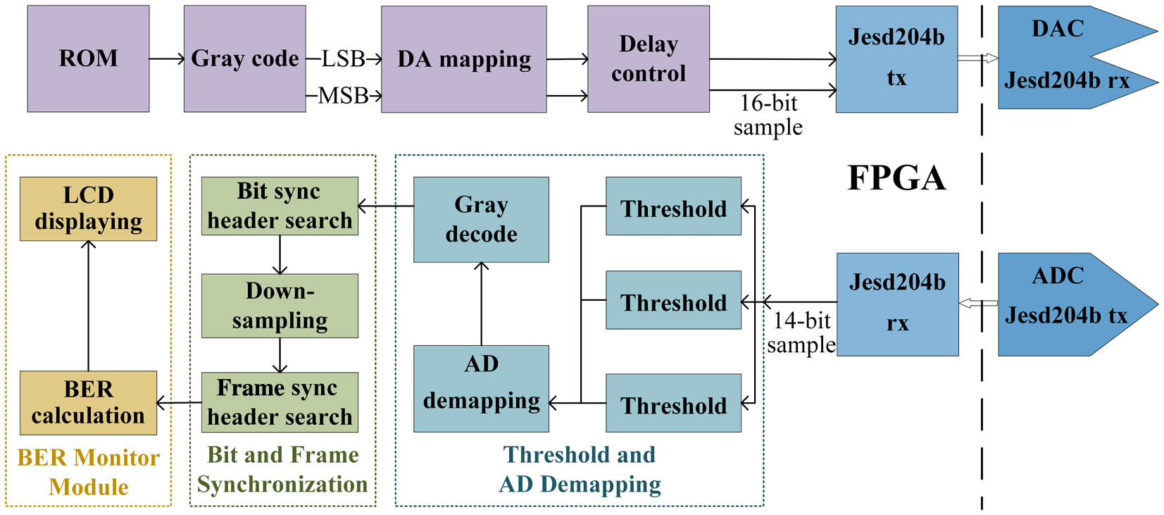
The process of the optical PAM-4 modulation and demodulation based on the FPGA is shown in Fig. 1. In the modulation unit, the read-only memory (ROM) stores the pseudo-random binary sequence (PRBS), the symbol sync header, and the frame sync header sequence. The bit stream is sent out periodically from the ROM with 2-bit width and mapped into the Gray code. The most significant bit (MSB) and least significant bit (LSB) of the 2-bit stream are separated into two links. Then, every binary symbol of each link is mapped to a sampling value and transmitted to the digital-to-analog converter (DAC), of which the resolution is 16 bits. A delay control module is designed to adjust the difference between the two links with an accuracy of 0.83 ns. Then, a Jesd204b protocol is used to complete the transmission between the FPGA and the DAC. Finally, two converters of the DAC output the MSB and LSB of the 2-bit stream in the form of an OOK signal, respectively.
![]()
Figure 1.Process of PAM-4 modulation and demodulation based on FPGA.
In the demodulation unit, the sampling rate of the analog-to-digital converter (ADC) is eight times the symbol rate, and the resolution is 14 bits. Every sampling value from the ADC is transmitted into the FPGA by another Jesd204b protocol and firstly enters the threshold calculation module. In the threshold and analog-to-digital (AD) demapping module, three thresholds of the PAM-4 signal are calculated by the method of accumulation and average. Every sampling value is demapped as a PAM-4 symbol using three thresholds and then decoded. In the next step, the symbol sync header sequence is used to perform symbol synchronization for determining the best sampling value among the eight sampling values of a symbol and down-sampling. The frame sync header sequence is employed to determine the start of the frame. In the bit error ratio (BER) monitor module, the demodulated signal is compared with the transmitted signal stored in the ROM, and the numbers of the error bits and received bits are counted. The latest BER is calculated according to the number of the error bits after every bits are received. Then, the BER is displayed on the liquid crystal display, which can be observed during the experiment. The process of the electrical PAM-4 modulation and demodulation is similar to the above, where only the digital-to-analog (DA) mapping is different. The data transmission between the FPGA and data converters is realized by using the Jesd204b protocol.
3. Experimental Setup
The experimental setup of the proposed optical PAM-4 UWOC system based on a fiber combiner is shown in Fig. 2. At the transmitter, two OOK or PAM-4 signals generated by an FPGA (KC705) were converted into an analog signal by a broadband DAC and amplified by two 37 dB AMPs (100 kHz to 75 MHz). Then, two identical variable electrical attenuators (VEA, KT3.0-30/1S-2S) were used to adjust the amplitude of the electrical signal. Two direct-current (DC) powers and signals were connected to two bias tees (Bias-T, ZHBT-4R2GW+, 10 to 4200 MHz) to drive two pigtailed blue-light LDs (NDB7875). By setting different attenuation coefficients and bias currents, two optical signals reached the optical power satisfying Eq. (10). The optical signals from LDs were injected into two input terminals of the fiber combiner (Xiri MPC ), with the remaining input terminal suspended, and the combining efficiency of the fiber combiner was measured to be 73%. The output end of the fiber combiner was connected to a collimator using an armored fiber, which was assembled in a sealed cabin, as shown in Fig. 2(b). The collimator was fixed in the center of the watertight cabin by a 3D printed component.
![]()
Figure 2.Experimental setup diagram of the proposed UWOC system based on the FPGA and a fiber combiner. Inserts: (a) the FPGA, (b) the transmitter cabin, (c) the receiver cabin, and (d) the transmitter cabin in a 50 m swimming pool.
At the receiver, a PMT (Hamamatsu H14447) was placed in another watertight cabin and converted the optical signal to the electrical signal. The electrical signal was connected to the outside through a watertight connector and was amplified by an AMP (ZHL-6A-S+, 2.5 kHz to 500 MHz). The FPGA and a broadband ADC performed the real-time demodulation after receiving the electrical signal. To verify the accuracy of the demodulation of the real-time processing, the data captured by the ADC was also recorded on a computer by the logic analyzer of the FPGA developing platform for offline processing. Finally, the data captured by an oscilloscope (OSC, Agilent Technologies DSO-X 4104A, 5 GSa/s) were used for offline analysis and plotting eye diagrams. The P-I and V-I curves of the LD are shown in Fig. 3(a). The normalized frequency response of the system was measured by a network analyzer (Hewlett Packard 8753D), as depicted in Fig. 3(b).
![]()
Figure 3.(a) P-I and V-I curves of the LD; (b) normalized frequency responses of the system.
4. Experimental Results and Discussion
In this work, the data rate is limited by the system bandwidth, the sampling rate of the ADC, the frequency division coefficient, and the reference frequency of the clock chip. Therefore, the proposed system was experimented with three data rates of 125, 150, 187.5 Mbit/s, respectively.
First, we studied the nonlinearity of the proposed system. A 25 MHz triangular wave generated by an arbitrary waveform generator (AWG) was transmitted in links A and B, respectively, and the corresponding signals A and B received by the PMT were sampled by an OSC. Figure 4 shows the transfer curve of the UWOC system, which indicates that the system has severe nonlinear effects.
![]()
Figure 4.Transfer curve of the UWOC system.
The relationship between attenuation values of VEA and real-time BER under different bias currents with a 150 Mbit/s data rate is illustrated in Fig. 5. The devices used in the two links are the same, so the parameters of the two links are the same in the electrical PAM-4 scheme. From Fig. 5(a), the optimal bias current and attenuation value with minimum real-time BER are 0.34 A and 14 dB, respectively. In the optical PAM-4 scheme, the bias current and attenuation values of link A are set to be 0.34 A and 14 dB, respectively, and then we changed the bias current and attenuation value of link B. Figure 5(b) shows that the optimal attenuation value also decreases as the bias current decreases. To maintain the integrity of the signal and increase the emitting optical power, the optimal bias current and attenuation values for signal B are set to 0.26 A and 17 dB, respectively.
![]()
Figure 5.Relationships between attenuation of VEA and real-time BER under different bias currents in (a) the electrical PAM-4 scheme and (b) the optical PAM-4 scheme.
After determining the optimal parameters of the system, the performance of the proposed system was verified in a 50 m standard swimming pool. The estimated attenuation coefficient for water is 0.5671 dB/m (0.1307 m−1) after removing the measured geometric loss. The BERs of the real-time processing and offline processing at different data rates are shown in Fig. 6. Compared with the electrical PAM-4 scheme, the real-time BERs of the optical PAM-4 scheme at different data rate are lower. The BER of offline processing is close to that of real-time processing, which verifies the accuracy of real-time processing. The crystal oscillators of the FPGAs used in the transmitter and the receiver are not strictly identical, so there exists a frequency offset between them. Through offline analysis, we found that the frequency offset at a data rate of 125 Mbit/s is higher than that of 150 Mbit/s due to different settings of the clocks. With the same frame length, the demodulation of the 125 Mbit/s data rate is more prone to error bits, which reduces the BER performance. The real-time BER of the optical PAM-4 UWOC system is at a data rate of 187.5 Mbit/s in continuous 40 s, which is below the hard-decision forward error correction threshold of . In offline processing, the ADC can only record the data within tens of milliseconds, which leads to accidental errors due to dynamic changes in the underwater channel generated by the circulatory system.
![]()
Figure 6.BERs of the real-time processing and offline processing at different data rates.
Figure 7 illustrates the error vector magnitude (EVM) at different data rates in the optical and electrical PAM-4 UWOC system. The EVM of the electrical PAM-4 scheme at a data rate of 150 Mbit/s is 22.4048%, and the EVM of the optical PAM-4 scheme at a data rate of 187.5 Mbit/s is 22.5587%. The data rate of the optical PAM-4 scheme is increased by 25% at a close EVM. By comparing the eye diagram of the electrical and optical PAM-4 schemes at the data rate of 187.5 Mbit/s, as shown in insets of Fig. 7, it can be affirmed that the eye diagram of the optical PAM-4 scheme is more evenly distributed.
![]()
Figure 7.EVM at different data rates in the optical and electrical PAM-4 UWOC system. Inserts: (a) electrical PAM-4 scheme at 187.5 Mbit/s, (b) optical PAM-4 scheme at 187.5 Mbit/s.
Figure 8 illustrates the ratio of the amplitude difference between adjacent levels of the PAM-4 signals at different data rates in the electrical and optical PAM-4 schemes. According to Eq. (6), we define , , and as three amplitude differences between adjacent amplitudes of the received PAM-4 signal, and is the total amplitude difference of the received PAM-4 signal. Then, we can further get
![]()
Figure 8.Ratio of the amplitude difference at different data rates in the optical and electrical PAM-4 UWOC system.
5. Conclusion
In this paper, we demonstrated a real-time optical superimposition PAM-4 UWOC system based on the FPGA and fiber combiner. Compared with the conventional electrical PAM-4 UWOC system whose LDs transmit the same PAM-4 signal, the optical PAM-4 scheme using two pigtailed LDs and a fiber combiner effectively reduces the nonlinearity of the system despite some optical power loss. At the receiver, the system used a high-bandwidth PMT as the detector, which ensures a high data rate with a large attenuation coefficient. In the swimming pool experiment, the optical PAM-4 UWOC system successfully reached a transmission distance of 50 m at a data rate of 187.5 Mbit/s in the real-time processing scheme, while that of the electrical PAM-4 scheme was only 150 Mbit/s in the same condition. This work explores the potential of the optical superimposition using the fiber combiner for UWOC and provides a new solution for alleviating the nonlinearity of UWOC systems with a high data rate.
References
[1] J. Xu. Underwater wireless optical communication: why, what, and how? [Invited]. Chin. Opt. Lett., 17, 100007(2019).
[2] S. Zhu, X. Chen, X. Liu, G. Zhang, P. Tian. Recent progress in and perspectives of underwater wireless optical communication. Prog. Quantum Electron., 73, 100274(2020).
[3] J. Lin, Z. Du, C. Yu, W. Ge, W. Lü, H. Deng, C. Zhang, X. Chen, Z. Zhang, J. Xu. Machine-vision-based acquisition, pointing, and tracking system for underwater wireless optical communications. Chin. Opt. Lett., 19, 050604(2021).
[4] C. Fei, X. Hong, J. Du, G. Zhang, Y. Wang, X. Shen, Y. Lu, Y. Guo, S. He. High-speed underwater wireless optical communications: from a perspective of advanced modulation formats [Invited]. Chin. Opt. Lett., 17, 100012(2019).
[5] C. Lu, J. Wang, S. Li, Z. Xu. 60 m/2.5 Gbps underwater optical wireless communication with NRZ-OOK modulation and digital nonlinear equalization. Conference on Lasers and Electro-Optics, SM2G.6(2019).
[6] M. Zhao, X. Li, X. Chen, Z. Tong, W. Lyu, Z. Zhang, J. Xu. Long-reach underwater wireless optical communication with relaxed link alignment enabled by optical combination and arrayed sensitive receivers. Opt. Express, 28, 34450(2020).
[7] X. Yang, Z. Tong, Y. Dai, X. Chen, H. Zhang, H. Zou, J. Xu. 100 m full-duplex underwater wireless optical communication based on blue and green lasers and high sensitivity detectors. Opt. Commun., 498, 127261(2021).
[8] X. Chen, X. Yang, Z. Tong, Y. Dai, X. Li, M. Zhao, Z. Zhang, J. Zhao, J. Xu. 150 m/500 Mbps underwater wireless optical communication enabled by sensitive detection and the combination of receiver-side partial response shaping and TCM technology. J. Light. Technol., 39, 4614(2021).
[9] Y. Dai, X. Chen, X. Yang, Z. Tong, Z. Du, W. Lyu, C. Zhang, H. Zhang, H. Zou, Y. Cheng, D. Ma, J. Zhao, Z. Zhang, J. Xu. 200-m/500-Mbps underwater wireless optical communication system utilizing a sparse nonlinear equalizer with a variable step size generalized orthogonal matching pursuit. Opt. Express, 29, 32228(2021).
[10] C. Fei, Y. Wang, J. Du, R. Chen, N. Lv, G. Zhang, J. Tian, X. Hong, S. He. 100-m/3-Gbps underwater wireless optical transmission using a wideband photomultiplier tube (PMT). Opt. Express, 30, 2326(2022).
[11] J. Huang, C. Li, J. Dai, R. Shu, L. Zhang, J. Wang. Real-time and high-speed underwater photon-counting communication based on SPAD and PPM symbol synchronization. IEEE Photon. J., 13, 7300209(2021).
[12] X. Hong, C. Fei, G. Zhang, J. Du, S. He. Discrete multitone transmission for underwater optical wireless communication system using probabilistic constellation shaping to approach channel capacity limit. Opt. Lett., 44, 558(2019).
[13] X. Chen, W. Lyu, Z. Zhang, J. Zhao, J. Xu. 56-m/3.31-Gbps underwater wireless optical communication employing Nyquist single carrier frequency domain equalization with noise prediction. Opt. Express, 28, 23784(2020).
[14] J. Liu, Z. Gu, B. Zheng, L. Zhao, Z. Gong. A design of underwater wireless laser communication system based on PPM modulating method. Ocean–Shanghai(2016).
[15] J. Wang, C. Tian, X. Yang, W. Shi, Q. Niu, T. Aaron Gulliver. Underwater wireless optical communication system using a 16-QAM modulated 450-nm laser diode based on an FPGA. Appl. Opt., 58, 4553(2019).
[16] M. Chen, P. Zou, L. Zhang, N. Chi. Demonstration of a 2.34 Gbit/s real-time single silicon-substrate blue LED-based underwater VLC system. IEEE Photon. J., 12, 7900211(2020).
[17] J. Li, J. Li, B. Yang, D. Ye, L. Wang, K. Fu, J. Piao, Y. Wang. A real-time, full-duplex system for underwater wireless optical communication: hardware structure and optical link model. IEEE Access, 8, 109372(2020).
[18] Y. Shao, R. Deng, J. He, K. Wu, L.-K. Chen. Real-time 2.2-Gb/s water-air OFDM-OWC system with low-complexity transmitter-side DSP. J. Light. Technol., 38, 5668(2020).
[19] Z. Jiang, C. Gong, Z. Xu. Achievable rates and signal detection for photon-level photomultiplier receiver based on statistical non-linear model. IEEE Trans. Wirel. Commun., 18, 6015(2019).
[20] H. M. Salgado, J. J. O’Reilly. Volterra series analysis of distortion in semiconductor laser diodes. Optoelectron., 138, 379(1991).
[21] L. Ding, S. Member, G. T. Zhou, S. Member, D. R. Morgan, Z. Ma, J. S. Kenney, J. Kim, C. R. Giardina. Using memory polynomials. IEEE Trans. Commun., 52, 159(2004).
[22] T. Fath, C. Heller, H. Haas. Power level stepping. J. Light. Technol., 31, 1734(2013).
[23] A. D. Griffiths, M. S. Islim, J. Herrnsdorf, J. J. D. McKendry, R. Henderson, H. Haas, E. Gu, M. D. Dawson. CMOS-integrated GaN LED array for discrete power level stepping in visible light communications. Opt. Express, 25, A338(2017).
[24] M. Kong, Y. Chen, R. Sarwar, B. Sun, Z. Xu, J. Han, J. Chen, H. Qin, J. Xu. Underwater wireless optical communication using an arrayed transmitter/receiver and optical superimposition-based PAM-4 signal. Opt. Express, 26, 3087(2018).
[25] Y. Yang, C. Chen, P. Du, X. Deng, J. Luo, W.-D. Zhong, L. Chen. Low complexity OFDM VLC system enabled by spatial summing modulation. Opt. Express, 27, 30788(2019).

Set citation alerts for the article
Please enter your email address
© Copyright 2018-2021 | Chinese Laser Press. All Rights Reserved 沪ICP备15018463号-20