• Photonics Research
  • Vol. 7, Issue 3, 274 (2019)
Zhen Liao, Guo Qing Luo*, Ben Geng Cai, Bai Cao Pan, and Wen Hui Cao
Author Affiliations
  • Key Laboratory of RF Circuits & System of Ministry of Education, Institute of Antennas and Microwave Technology, Hangzhou Dianzi University, Xiasha High Education Park, Hangzhou 310018, China
  • show less
    DOI: 10.1364/PRJ.7.000274 Cite this Article Set citation alerts
    Zhen Liao, Guo Qing Luo, Ben Geng Cai, Bai Cao Pan, Wen Hui Cao. Subwavelength negative-index waveguiding enabled by coupled spoof magnetic localized surface plasmons[J]. Photonics Research, 2019, 7(3): 274 Copy Citation Text show less
    (a) Magnetic field amplitude intensity detected at the center of the resonators; the inset is a schematic illustration of the metallic spiral structure. (b) Current distribution at z=0, (c) magnetic field at x=0, (d) electric field at x=0.
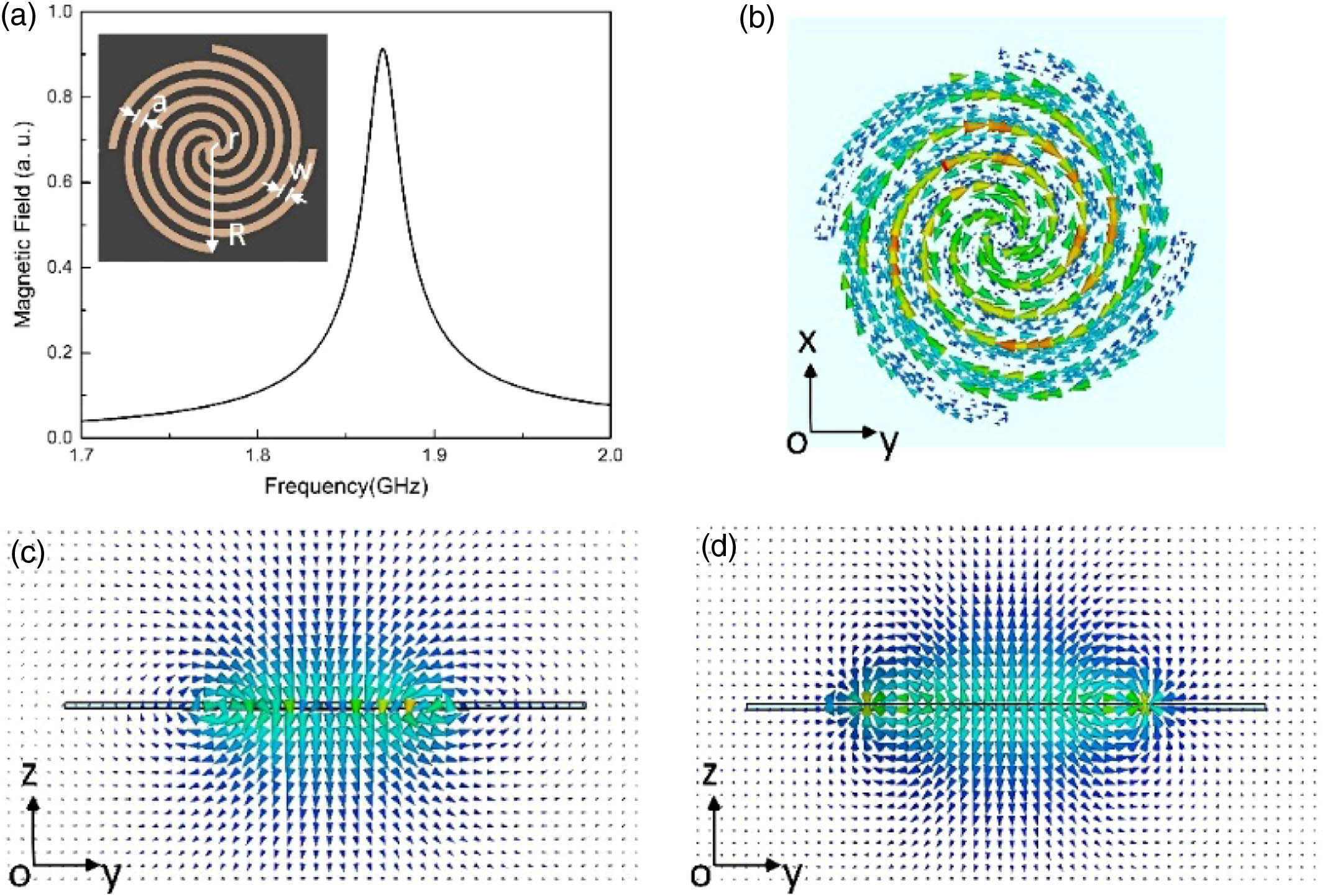
    Fig. 1. (a) Magnetic field amplitude intensity detected at the center of the resonators; the inset is a schematic illustration of the metallic spiral structure. (b) Current distribution at z=0, (c) magnetic field at x=0, (d) electric field at x=0.
    Simulation and measurement setups of the MSS dimers are shown in (a) and (b), respectively. The near-field response spectra for a single MSS (black line) and MSS dimer (red line) in (c) simulations and (d) measurements. The insets correspond to the electric field maps for the split higher and lower modes, respectively.
    Fig. 2. Simulation and measurement setups of the MSS dimers are shown in (a) and (b), respectively. The near-field response spectra for a single MSS (black line) and MSS dimer (red line) in (c) simulations and (d) measurements. The insets correspond to the electric field maps for the split higher and lower modes, respectively.
    Dispersion diagrams of infinite chains of metallic spiral structures based on Lagrangian analytical mode (black line), coupled mode theory (red symbols), and numerical simulation (square symbols). The blue dash line is the dispersion of the light in free space.
    Fig. 3. Dispersion diagrams of infinite chains of metallic spiral structures based on Lagrangian analytical mode (black line), coupled mode theory (red symbols), and numerical simulation (square symbols). The blue dash line is the dispersion of the light in free space.
    (a) Geometry of MSS chain. The red dash line indicates the observed cross section. The blue line indicates the observation line. The magnetic fields in the z=1 mm plane and y=0 plane are presented in (b) and (c), respectively.
    Fig. 4. (a) Geometry of MSS chain. The red dash line indicates the observed cross section. The blue line indicates the observation line. The magnetic fields in the z=1  mm plane and y=0 plane are presented in (b) and (c), respectively.
    (a) Magnetic field distributions along the z axis; (b) magnetic field distributions on the cross sections of the MSS chain at 1.84 and 1.88 GHz.
    Fig. 5. (a) Magnetic field distributions along the z axis; (b) magnetic field distributions on the cross sections of the MSS chain at 1.84 and 1.88 GHz.
    Magnetic field distributions along the MSS chain at different frequencies.
    Fig. 6. Magnetic field distributions along the MSS chain at different frequencies.
    (a) Simulation and experimental setup, (b) simulated and measured transmission spectra for the metamaterial resonator waveguides that consist of 10 MSSs, (c) simulated and (d) experimental amplitude of electric field Ez above the waveguide.
    Fig. 7. (a) Simulation and experimental setup, (b) simulated and measured transmission spectra for the metamaterial resonator waveguides that consist of 10 MSSs, (c) simulated and (d) experimental amplitude of electric field Ez above the waveguide.
    (a) Simulation of transmission spectra for adjacent MSSs with varying gap size from 10 to 0.5 mm. (b) Resonance frequency of two modes as a function of gap size. (c) Dispersion relation with different gap sizes. (d) Transmissions of MSS chains with different gap sizes.
    Fig. 8. (a) Simulation of transmission spectra for adjacent MSSs with varying gap size from 10 to 0.5 mm. (b) Resonance frequency of two modes as a function of gap size. (c) Dispersion relation with different gap sizes. (d) Transmissions of MSS chains with different gap sizes.
    Simulated vertical magnetic-field distributions of the waves on the MSS chain.
    Fig. 9. Simulated vertical magnetic-field distributions of the waves on the MSS chain.
    Zhen Liao, Guo Qing Luo, Ben Geng Cai, Bai Cao Pan, Wen Hui Cao. Subwavelength negative-index waveguiding enabled by coupled spoof magnetic localized surface plasmons[J]. Photonics Research, 2019, 7(3): 274
    Download Citation