
Guofeng Zhu, Zhenrong Dai, Xuewei Ju, Shuncong Zhong, Xiangfeng Wang, Feng Huang. On-Chip Terahertz Demultiplexer and Grating Coupler Based on Reverse Design[J]. Acta Optica Sinica, 2022, 42(9): 0913001
- Acta Optica Sinica
- Vol. 42, Issue 9, 0913001 (2022)
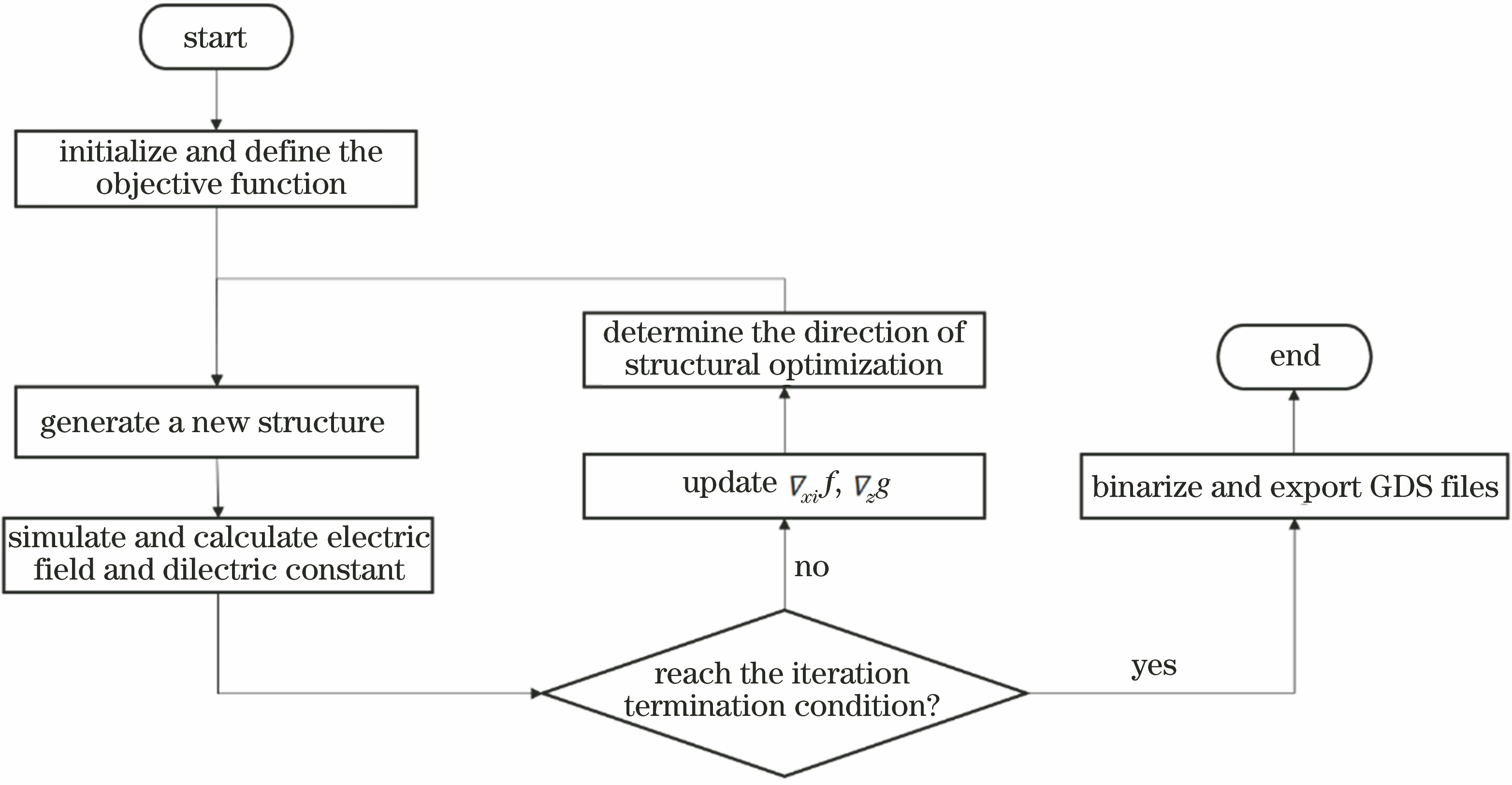
Fig. 1. Flowchart diagram of reverse design method
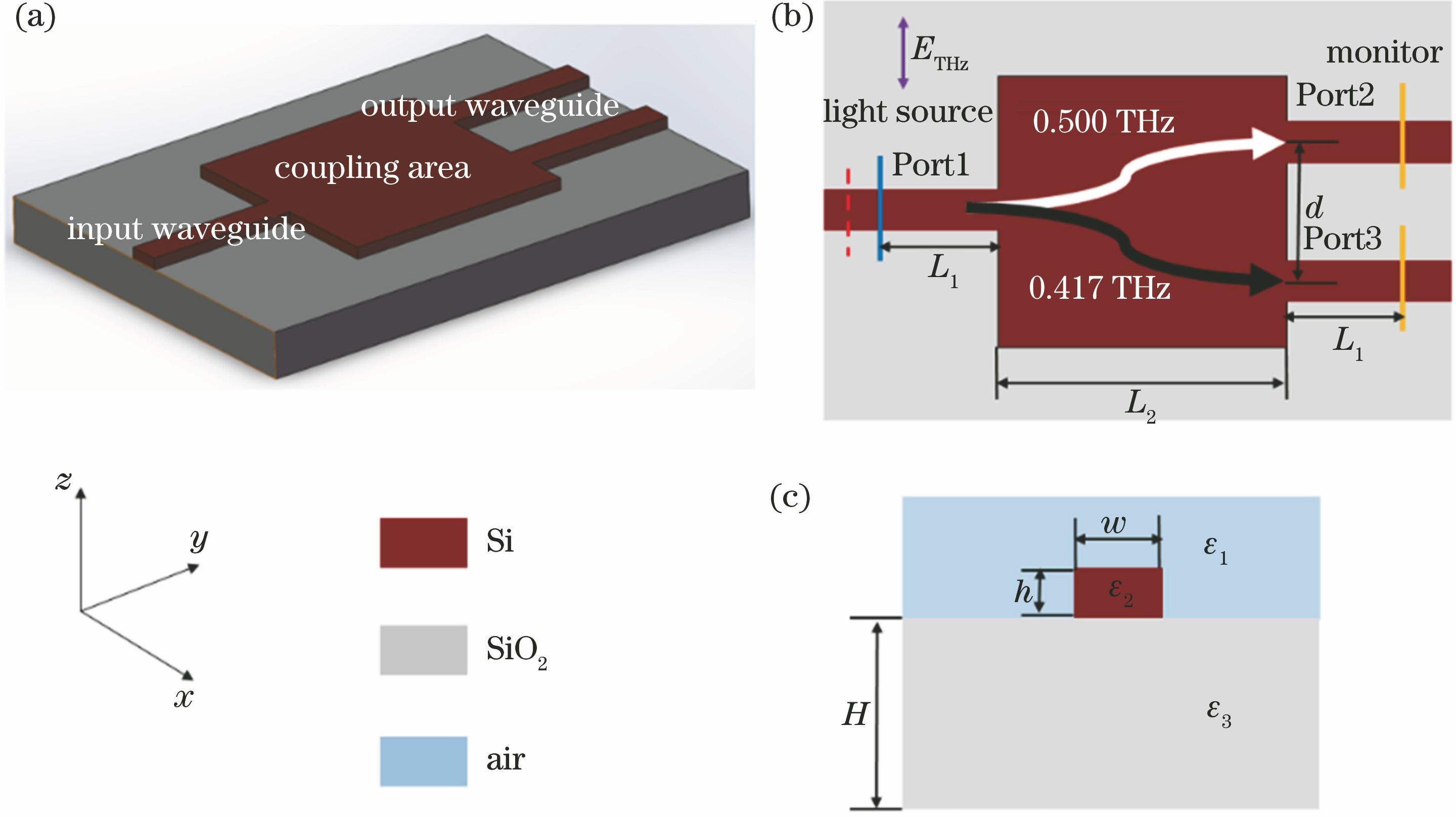
Fig. 2. Initial layout diagram of terahertz demultiplexer. (a) Initial three-dimensional structure; (b) top view of structure; (c) section view of waveguide structure
Fig. 3. Optimized structure and electric field intensity distribution of terahertz demultiplexer. (a) Top view of device; (b) electric field intensity diagram of 0.500 THz frequency for terahertz wave incident from Port1; (c) electric field intensity diagram of 0.417 THz frequency for terahertz wave incident from Port1; (d) electric field intensity diagram of 0.500 THz frequency for terahertz wave incident from Port2; (e) electric field intensity diagram of 0.417 THz frequency for terahertz wave terahertz incident from Port3
Fig. 4. Spectrum diagram of terahertz demultiplexer at two output ports. (a) Before bandwidth optimization; (b) after bandwidth optimization
Fig. 5. Schematic of initial layout of terahertz grating coupler. (a) Three-dimensional structure diagram of device; (b) top view of device; (c) symmetrical section view of device
Fig. 6. Optimized structure of grating coupler. (a) Variation curve of objective function value with number of iterations; (b) grating structure diagram after continuous optimization; (c) local magnification map after continuous optimization; (d) local magnification map after discrete optimization
Fig. 7. Discrete optimization structure and simulation results of grating coupler. (a) Optimized structure of terahertz grating coupler; (b) electric field intensity distribution diagram

Set citation alerts for the article
Please enter your email address
© Copyright 2018-2021 | Chinese Laser Press. All Rights Reserved 沪ICP备15018463号-20