• Chinese Journal of Lasers
  • Vol. 48, Issue 18, 1802003 (2021)
Zhanjiang Zhai1、2, Lin Zhao1、**, Yun Peng1、*, Jiao Zhu2, and Yang Cao1
Author Affiliations
  • 1Institute of Welding, Central Iron & Steel Research Institute, Beijing 100081, China;
  • 2NCS Testing Technology Co., Ltd., Beijing 100081, China
  • show less
    DOI: 10.3788/CJL202148.1802003 Cite this Article Set citation alerts
    Zhanjiang Zhai, Lin Zhao, Yun Peng, Jiao Zhu, Yang Cao. Low Cycle Fatigue Behavior of Laser Welded DP980 Steel Joints[J]. Chinese Journal of Lasers, 2021, 48(18): 1802003 Copy Citation Text show less
    Dimensions of fatigue specimen
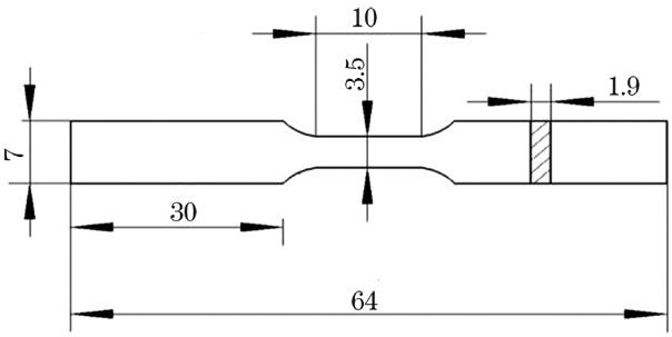
    Fig. 1. Dimensions of fatigue specimen
    Microstructure of DP980 steel
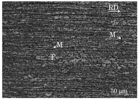
    Fig. 2. Microstructure of DP980 steel
    Morphologies of welding joints under different heat inputs. (a) 80 J·mm-1; (b) 100 J·mm-1; (c) 133 J·mm-1
    Fig. 3. Morphologies of welding joints under different heat inputs. (a) 80 J·mm-1; (b) 100 J·mm-1; (c) 133 J·mm-1
    Microhardness profiles of DP980 welding joints under different heat inputs
    Fig. 4. Microhardness profiles of DP980 welding joints under different heat inputs
    Typical tensile failure locations of DP980 welding joints and base material. (a) Base material; (b) L1 sample; (c) L2 sample; (d) L3 sample
    Fig. 5. Typical tensile failure locations of DP980 welding joints and base material. (a) Base material; (b) L1 sample; (c) L2 sample; (d) L3 sample
    Relationship between total strain amplitude and 2Nf for base material and DP980 welding joints
    Fig. 6. Relationship between total strain amplitude and 2Nf for base material and DP980 welding joints
    Microstructures of L2 sample. (a) Weld zone, supercritical HAZ, and intercritical HAZ; (b) subcritical HAZ
    Fig. 7. Microstructures of L2 sample. (a) Weld zone, supercritical HAZ, and intercritical HAZ; (b) subcritical HAZ
    Microstructures of subcritical HAZ under different heat inputs. (a) 80 J·mm-1; (b) 100 J·mm-1; (c) 133 J·mm-1
    Fig. 8. Microstructures of subcritical HAZ under different heat inputs. (a) 80 J·mm-1; (b) 100 J·mm-1; (c) 133 J·mm-1
    Variation of stress amplitudes of base material and DP980 welding joints under different strain amplitudes with numbers of cycles. (a) Base material; (b) L1 sample; (c) L2 sample; (d) L3 sample
    Fig. 9. Variation of stress amplitudes of base material and DP980 welding joints under different strain amplitudes with numbers of cycles. (a) Base material; (b) L1 sample; (c) L2 sample; (d) L3 sample
    Stabilized hysteresis loops at half fatigue life
    Fig. 10. Stabilized hysteresis loops at half fatigue life
    Low-cycle fatigue specimens of base material and joints
    Fig. 11. Low-cycle fatigue specimens of base material and joints
    Fatigue fracture domains of L2 and L3 samples. (a) Subcritical HAZ near L2 fracture; (b) subcritical HAZ near L3 fracture
    Fig. 12. Fatigue fracture domains of L2 and L3 samples. (a) Subcritical HAZ near L2 fracture; (b) subcritical HAZ near L3 fracture
    Macroscopic fatigue fracture morphologies of base material and welding joints when Δεt/2=0.3%. (a) Base material; (b) L1 sample; (c) L2 sample; (d) L3 sample
    Fig. 13. Macroscopic fatigue fracture morphologies of base material and welding joints when Δεt/2=0.3%. (a) Base material; (b) L1 sample; (c) L2 sample; (d) L3 sample
    Microscopic fatigue fracture morphologies of base material and welding joints when Δεt/2=0.3%. (a) Base material; (b) L1 sample; (c) L2 sample; (d) L3 sample
    Fig. 14. Microscopic fatigue fracture morphologies of base material and welding joints when Δεt/2=0.3%. (a) Base material; (b) L1 sample; (c) L2 sample; (d) L3 sample
    Macroscopic fatigue fracture morphologies of welding joints of L3 sample under different strain amplitudes. (a) Δεt/2=0.25%; (b) Δεt/2=0.3%; (c) Δεt/2=0.4%; (d) Δεt/2=0.5%
    Fig. 15. Macroscopic fatigue fracture morphologies of welding joints of L3 sample under different strain amplitudes. (a) Δεt/2=0.25%; (b) Δεt/2=0.3%; (c) Δεt/2=0.4%; (d) Δεt/2=0.5%
    Microscopic fatigue fracture morphologies of welding joints of L3 sample under different strain amplitudes. (a) Δεt/2=0.25%; (b) Δεt/2=0.3%; (c) Δεt/2=0.4%; (d) Δεt/2=0.5%
    Fig. 16. Microscopic fatigue fracture morphologies of welding joints of L3 sample under different strain amplitudes. (a) Δεt/2=0.25%; (b) Δεt/2=0.3%; (c) Δεt/2=0.4%; (d) Δεt/2=0.5%
    Sample No.Heat input /( J·mm-1)Laser power /WWelding speed /( m·min-1)Defocus quantity /mmFocal length /mmFlow rate /( L·min-1)
    L18020001.5030015
    L210020001.2030015
    L313320000.9030015
    Table 1. Welding parameters
    Sample No.Yield strength /MPaTensile strength /MPaElongation /%Product of strength and elongation /( GPa ·%)
    DP980706107114.015.0
    L1704102612.012.3
    L2737102810.510.8
    L3727101010.510.6
    Table 2. Mechanical properties of DP980 steel and welding joints
    Sample No.σf /MPabεfcNt /cycle
    DP9801860-0.11360.7407-0.64292536
    L11776-0.12001.1537-0.75611148
    L21625-0.11581.2824-0.77711122
    L31521-0.11270.2765-0.5862957
    Table 3. Low cycle fatigue parameters of DP980 steel and welding joints
    Zhanjiang Zhai, Lin Zhao, Yun Peng, Jiao Zhu, Yang Cao. Low Cycle Fatigue Behavior of Laser Welded DP980 Steel Joints[J]. Chinese Journal of Lasers, 2021, 48(18): 1802003
    Download Citation