
Rui-Rui Li, Wei-Ran Ye, Yi-Long Chen, Shu-Qian Chen, Wen-Hao Qi, Jin-Ming Cui, Yun-Feng Huang, Chuan-Feng Li, Guang-Can Guo. Generation of visible Raman operation laser by a fiber electro-optical modulator feedback loop[J]. Chinese Optics Letters, 2024, 22(2): 022702
- Chinese Optics Letters
- Vol. 22, Issue 2, 022702 (2024)
Abstract
Keywords
1. Introduction
Phase-coherent multi-tone lasers play a crucial role in the fields of modern information technology, e.g., optical microwave generation[1–4], and atomic physics, e.g. atomic clocks[5–7], quantum precision measurement[8–13], and qubits manipulation[14–18]. Among them, the stimulated Raman transition is widely used to manipulate atomic hyperfine qubits[19,20], and the Raman operation laser typically requires optical fields with gigahertz-level frequency difference to match the atomic energy levels. Furthermore, to obtain a long-term coherent time, the phase noise of the Raman operation laser has to be as low as possible. Plenty of technologies, such as optical phase locking (OPL)[21–25] and directly modulated lasers[26–29], have been developed to generate phase-coherent optical fields with gigahertz frequency difference for Raman operation. Among these technologies, OPL typically necessitates two separate laser sources and complex electrical feedback controls and suffers from poor robustness and high system complexity.
As a comparison, directly modulated lasers, which apply a low noise driving signal on acousto- or electro-optical modulators (AOMs or EOMs) to directly diffract a single laser, feature quite good stability and compact structures. The low bandwidth of AOMs and the narrow tuning range of resonant EOMs limit the performance of the directly modulated laser system. However, fiber EOMs (FEOMs), which possess a gigahertz bandwidth and wide tuning range, are now widely used in directly modulated lasers. Most of opeartion wavelengths of FEOMs are infrared or telecom (1550 nm), which are far away from the lines of the atomic qubits. To acquire considerable Rabi frequency, it necessitates a second-harmonic generation (SHG) process to down-convert operation wavelengths of FEOMs to wavelengths closer to the lines. In such systems, despite directly-modulated lasers conserving the phase noise performance of the driving signal, it degenerates with the external perturbations, e.g., the perturbations from the SHG process, because of the lack of active suppression for the phase noise. Thus, an active phase noise suppression subsystem is crucial for enhancing the performance of directly-modulated lasers.
In this work, we demonstrate a compact, robust, and low phase noise scheme that utilizes an FEOM feedback loop to generate multi-tone lasers and suppress the phase noise. We utilize an FEOM driven by a voltage-controlled oscillator (VCO) to modulate a monochromatic 1064 nm laser to generate the desired sidebands. The frequency difference between sidebands equals the hyperfine splitting of the qubit[30]. Then, the modulated laser is converted to a 532-nm three-tone laser via second harmonic generation (SHG) conversion. After SHG conversion, we then inject the 1064-nm laser into a fast photoelectric detector (FPD) to acquire the beat note signal (BNS). A digital PLL is employed to control the output frequency of the VCO to narrow the linewidth of the BNS (~1 Hz) and suppress the phase noise. We find that the phase noise of our scheme is lower than that of the case without feedback control in the low-frequency domain, and it reaches with a loop bandwidth of 20 kHz. Moreover, by replacing the luxury and bulky commercial signal generator with inexpensive and miniature devices, our scheme significantly reduces the system’s complexity and cost. Our scheme can rebuild a closed loop within 150 µs when encountering a hopping of reference signal, indicating its frequency turning agility. Those features make this scheme promising for application in some extreme environments, e.g., atomic clocks in space and portable atomic gravimeters transported by trucks.
Sign up for Chinese Optics Letters TOC. Get the latest issue of Chinese Optics Letters delivered right to you!Sign up now
2. Experimental Setup
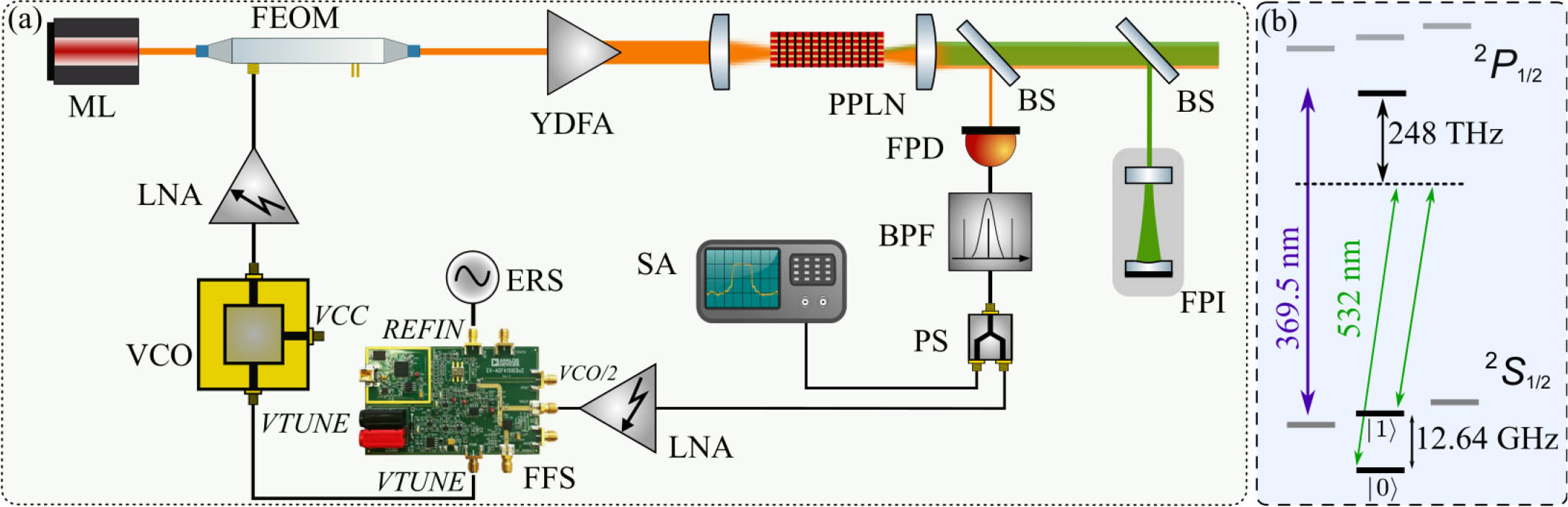
The schematic of our experimental setup is shown in Fig. 1(a). Here, we adopt a master oscillator power amplifier (MOPA) configuration, which only contains a single laser to simplify the system architecture and improve the maintainability. A 1064 nm monochromatic laser (ML, Koheras BASIK Y10, NKT Photonics, Japan) that only outputs one frequency component is used as a seed laser. To narrow the linewidth and stabilize the long-term frequency drift of the ML, we lock the frequency of the ML to an ultra-stable Fabry–Pérot cavity with Pound–Drever–Hall technology[31]. The optical field of the ML is written as
![]()
Figure 1.(a) Schematic of the experimental setup. Some concerned ports of the FFS chip and the VCO chip are marked by italics in the figure. (b) Energy level schematic of the 171Yb+ qubits. The energy levels associated with the stimulated Raman transition (SRT). Here, we utilize two 532 nm optical fields with a frequency difference of 12.64 GHz to implement the SRT. The transition wavelength for Doppler cooling is 369.5 nm. ML, monochromatic laser; FEOM, fiber electro-optic modulator; YDFA, ytterbium-doped fiber amplifier; BS, beam splitter; PPLN, periodically polarized lithium niobate; LNA, low-noise amplifier; FPD, fast photoelectric detector; VCO, voltage-controlled oscillator; ERS, external reference signal; PS, power splitter; SA, spectrum analyzer; FFS, fractional-N frequency synthesizer; FPI, Fabry–Pérot interferometer.
Then, the output beam of the ML is sent into an FEOM (iXblue, NIR-MX-LN-20, France) driven by the VCO (Mini-Circuits, ROS-6520C-119+, USA), of which the tuning range is 6250 MHz to 6630 MHz, to generate multi-tone lasers. In our practical application shown in this work, we adopt a fiber Mach–Zehnder modulator that operates at carrier-suppression and double-sideband (CS-DSB) modulation to suppress redundant frequency components generated by EOM modulation, as we described in detail in Ref. [29]. One can also adopt a phase modulator as a substitute of the Mach-Zehnder modulator since they have the same principle that generates such phase-coherent multi-tone lasers. In our case, we lock the frequency of the BNS to the hyperfine ground state splitting of the qubit, i.e., and . The hyperfine ground state splitting is 12.64 GHz, and we denote it as . Here, the Raman operation laser is the 532-nm visible laser with 248 THz detuning from the state. The relevant energy levels are shown in Fig. 1(b). Hence, the driving frequency of the FEOM (or the output frequency of the VCO), which is denoted as , has to be locked to half of the . The optical fields following the FEOM is written as
Here, we assume that the amplitudes of the optical fields is normalized.
Multi-tone lasers are subsequently amplified by an Yb-doped fiber amplifier (YDFA, Precilasers, YDFA-SF-1064-8 W-CW, China), and the maximum output power of the YDFA is 8 W. The amplified laser is focused by a lens and then sent to a PPLN crystal where the second-harmonic generation (SHG) occurs. Here, the SHG process converts the laser from the infrared domain to the visible domain to obtain a higher effective Rabi frequency. After SHG conversion, part of the 1064-nm lasers have been converted to 532-nm lasers, the rest of them are emitted from the PPLN crystal and are sampled by a beam splitter (BS). The sample 1064 nm laser is sent to a fast photoelectric detector (FPD) with a sensitivity of 0.7 A/W@1550 nm and a bandwidth of 20 GHz (Keyang Photonics, KY-APRM-20G, China). The power of the incident laser should be close to the saturation intensity of the FPD (500 µW@1550 nm) to acquire a signal-to-noise ratio as high as possible, given that the dark current of this FPD is fixed at 50 nA. The output signal of the FPD is written as
The direct current (DC) component and high frequency components in the output signal of the FPD are filtered by a band-pass filter (BPL, A-INFO, China, 12.55 GHz to 13.30 GHz). Subsequently, a power divider splits the BNS into two portions. One is sent to a spectrum analyzer (SA) to monitor the spectrum of the BNS and the performance of the phase-locked system. Meanwhile, the other portion is sent to a broad-bandwidth and low-noise amplifier (Mini-Circuits, ZVA-213-S+, USA, 0.8 GHz to 21 GHz). The amplified BNS is written as
The BNS is sent to a fractional-N frequency synthesizer (FFS) chip (ADI, ADF4159, USA) of which the output frequency is up to 13 GHz. The ADF4159 consists of a low-noise digital frequency and phase discriminator (PFD), a precision charge pump, and a programmable reference divider. The input RF signal, i.e., the BNS, is connected to the port while an ERS from a rubidium frequency standard (SRS, FS725, USA) is connected to the REFIN port. The ERS, of which the frequency is 10 MHz, possesses an ultra-low phase noise of , a temperature stability of ( to ), and an aging rate of to satisfy the strict requirements of the PLL.
The chip digitally divides the BNS by a factor of (depending on the frequency of the ERS, the , and the locking frequency) and the ERS by a factor of (1 in our scheme) and then sends them to the PFD, where the frequencies and phases of both divided signals are being compared. The phase error signal generated by the PFD is subsequently sent to a predefined low-pass loop filter and transferred into a control voltage via the precision charge pump. The control voltage signal is written as
In the case that locking frequency equals the , we have
Thus, Eq. (5) turns to zero and the output frequency of the VCO is locked at when the phase-locked loop is established.
The output signal of the VCO is amplified by another LNA to ensure that the FEOM outputs sufficient laser power that exceeds the threshold of the YDFA. The low-pass loop filter is designed to filter out the high-frequency noise that existed in the control voltage. A high loop bandwidth will introduce high-frequency noise and degrade the performance of the PLL, while a low loop bandwidth will limit the response speed of the system. Therefore, we design a loop filter with a bandwidth of 20 kHz as a trade-off for the above conditions.
Two LNAs, the VCO, the FPD, and the FFS are all powered by isolated linear power supplies to avoid the detrimental effect of electrical noise.
3. System Characterization
We connect the monitor port of the PD to an SA to acquire the power density spectrum of the BNS. Figure 2(a) shows a comparison between the spectrum of the BNS when the system is free running (red line) and the loop is closed (black line), respectively. For both spectra, the resolution bandwidth (RBW) and the video bandwidth (VBW) of the SA are set to 10 Hz and 10 Hz, respectively. The center frequency of the BNS equals the when the loop is closed. There are two significant differences between these two spectra.
![]()
Figure 2.(a) Comparison between the spectrum of the BNS when the system is free running and the loop is closed. The frequency span is set to 100 kHz, and the RBW and the VBW are both set to 10 Hz. (b) Expanded view of the BNS when the loop is closed. The frequency span is set to 100 Hz. The RBW is set to 1 Hz, and the VBW is set to 10 Hz.
In the case of free running system, the BNS has a wide line width while the phase-locked loop successfully narrows the linewidth. Moreover, in the case of a closed loop, a low and wide peak appears at the offset frequency of near 20 kHz (matches well with our design) in the spectrum. This mainly results from the high gain within the bandwidth of the loop filter. Those undesired peaks appearing at frequencies 27 kHz (black line) and 37 kHz (red line) may be caused by the unquenched noise from the linear power supply. Figure 2(b) shows an expanded view of the BNS when the loop is closed. In this case, the RBW is set to 1 Hz and the VBW is set to 10 Hz. We calculate the 3 dB linewidth of the BNS when the loop is close to about 1 Hz.
To characterize the phase noise performance of the phase-locked system, we replace the SA with a phase-noise analyzer to measure the phase noise of the BNS in the case of the FEOM driven by the FFS. As a comparison, we also measure the phase noise of the BNS in the case of the FEOM directly driven by a commercial signal generator (Rohde & Schwarz, SMB100A, Germany), as in our previous scheme. The measured phase noises are shown in Fig. 3. The phase noise of the BNS, in the case that the FEOM is driven by the FFS, is lower than that in the case of the FEOM driven by the SMB100A in the range of 1 Hz to 100 Hz. The phase noise reaches a flat floor of in the offset frequency range of 100 Hz to 5 kHz, and then it bumps up to at 20 kHz, which is the bandwidth of the loop filter. The phase noise is below when the offset frequency is higher than 100 kHz.
![]()
Figure 3.Phase noise comparison between our scheme (when the loop is closed) and the scheme when the FEOM is directly driven by a commercial signal generator. The phase noise is measured by a phase noise analyzer rather than an SA.
Typically, within the bandwidth of the loop filter, the phase noise is related to the ERS, the factor , and the charge pump. Given that our ERS has ultra-low phase noise, the phase noise is dominated by the latter two. On the one hand, the phase noise can be suppressed by lowering the factor , which needs to increase the frequency of the ERS due to the fixed locking frequency of the closed loop. On the other hand, the current noise of the charge pump will deteriorate the phase noise. Thus, employing a low-noise power supply for the charge pump helps to obtain a better performance of the phase noise. In addition, electrical shielding added to different devices also helps to improve the performance of the phase noise.
The dynamic performance of the PLL is crucial to flexibly tune the frequency gap between the multi-tone lasers, which has the potential to be applied to manipulating multiple species of ion qubits. We measure the re-locking time of the system to characterize its dynamic performance, which refers to the time interval the PLL takes to recover a locked state after a sudden change of locking frequency. Initially, the system is stably locked at , which is 12.64 GHz. The voltage of the VTUNE port is 1.24 V, corresponding to the output frequency of 6.32 GHz. At the time , we suddenly apply a frequency hopping to shift the locking frequency to 12.74 GHz. The voltage change of the VTUNE port with time is recorded by an oscilloscope, as shown in Fig. 4.
![]()
Figure 4.Dynamic performance of the PLL system. The locking frequency changes at the time t = 0. The voltage change of the VTUNE port with time is recorded by an oscilloscope. The rising time and the re-locking time are about 20 µs and 150 µs, respectively, according to the measured result.
When the locking frequency is increased, the voltage of the VTUNE port is simultaneously increased to track the locking frequency, and the rise time is 20 µs. It takes the PLL about 150 µs to relock after a feedback process, which is indicated by the damped oscillation at the beginning of the waveform. By widening the bandwidth of the PLL, we can obtain a shorter re-locking time.
For our application, for manipulating the quantum state of the qubit via SRT, the phase-locked 1064-nm laser is sent to a PPLN crystal to generate a 532-nm multi-tone laser. The optical field of the 532-nm laser is written as
When the PLL is locked at the frequency of 12.49 GHz and 12.64 GHz (which is ), the corresponding sideband spectra of the 532-nm laser are recorded and are shown in Figs. 5(a) and 5(b), respectively. It is worth noting that the free spectral range (FSR) of the FPI is 1.49 GHz. In Fig. 5(a), the frequency difference between the sidebands with lower amplitude and the sideband with maximum amplitude is , which matches the reference frequency of 12.49 GHz. When the reference frequency switches to 12.64 GHz, the position of the sidebands in 532-nm laser changes correspondingly. The result indicates that the generated multi-tone 532-nm laser can manipulate the qubit via SRT.
![]()
Figure 5.Sideband spectra of the 532-nm laser measured with an FPI. When the driving frequency of the FEOM changes, the sidebands appear at the corresponding positions.
4. Conclusion and Outlook
To conclude, we demonstrate a scheme that employs an FEOM feedback loop to generate multi-tone lasers and suppress the phase noise. In this scheme, a monochromatic laser is modulated by an FEOM driven by the VCO to generate sidebands with gigahertz frequency difference. The modulated laser is amplified by a YDFA and converted to a visible Raman operation laser via SHG. The BNS is then stabilized by a digital feedback loop to suppress the phase noise caused by external perturbations. The phase noise of our scheme is up to 7.4 dB lower than that of the scheme in which the FEOM is driven by a commercial signal generator in a low-frequency domain. Distinct from the OPL schemes and direct modulation schemes, our scheme only requires a single laser and replaces the commercial signal generator with easily available and inexpensive devices, which significantly reduces the system’s complexity and cost.

Set citation alerts for the article
Please enter your email address
© Copyright 2018-2021 | Chinese Laser Press. All Rights Reserved 沪ICP备15018463号-20