• High Power Laser Science and Engineering
  • Vol. 3, Issue 1, 010000e1 (2015)
Hong Jin Kong1, Sangwoo Park1, Seongwoo Cha1, Heekyung Ahn1, Hwihyeong Lee1, Jungsuk Oh1, Bong Ju Lee2, Soungwoong Choi2, and and Jom Sool Kim3
Author Affiliations
  • 1Department of Physics, Korea Advanced Institute of Science and Technology (KAIST), 291 Daehak-ro, Yuseong-gu, Daejeon 305-701, Republic of Korea
  • 2Department of Advanced Green Energy and Environment, Handong Global University, Heunghae-eup, Buk-gu, Pohang-si, Gyeongbuk 791-708, Republic of Korea
  • 3Laser Spectronix, 219 Gasan digital 1-ro, Geumcheon-gu, Seoul 153-704, Republic of Korea
  • show less
    DOI: 10.1017/hpl.2014.49 Cite this Article Set citation alerts
    Hong Jin Kong, Sangwoo Park, Seongwoo Cha, Heekyung Ahn, Hwihyeong Lee, Jungsuk Oh, Bong Ju Lee, Soungwoong Choi, and Jom Sool Kim. Conceptual design of the Kumgang laser: a high-power coherent beam combination laser using SC-SBS-PCMs towards a Dream laser[J]. High Power Laser Science and Engineering, 2015, 3(1): 010000e1 Copy Citation Text show less
    The schematic diagram of the Kumgang laser system.
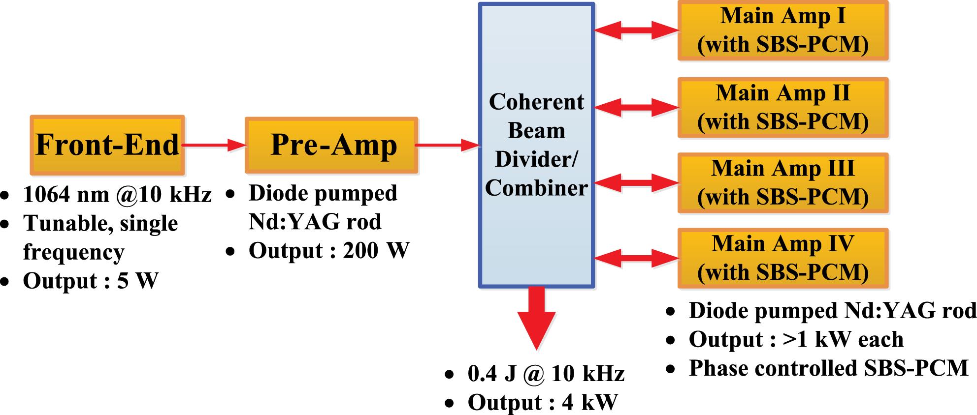
    Fig. 1. The schematic diagram of the Kumgang laser system.
    The MOPA beam combination laser with the amplitude combining method using PBSs: EM1–EM6, energy meters.
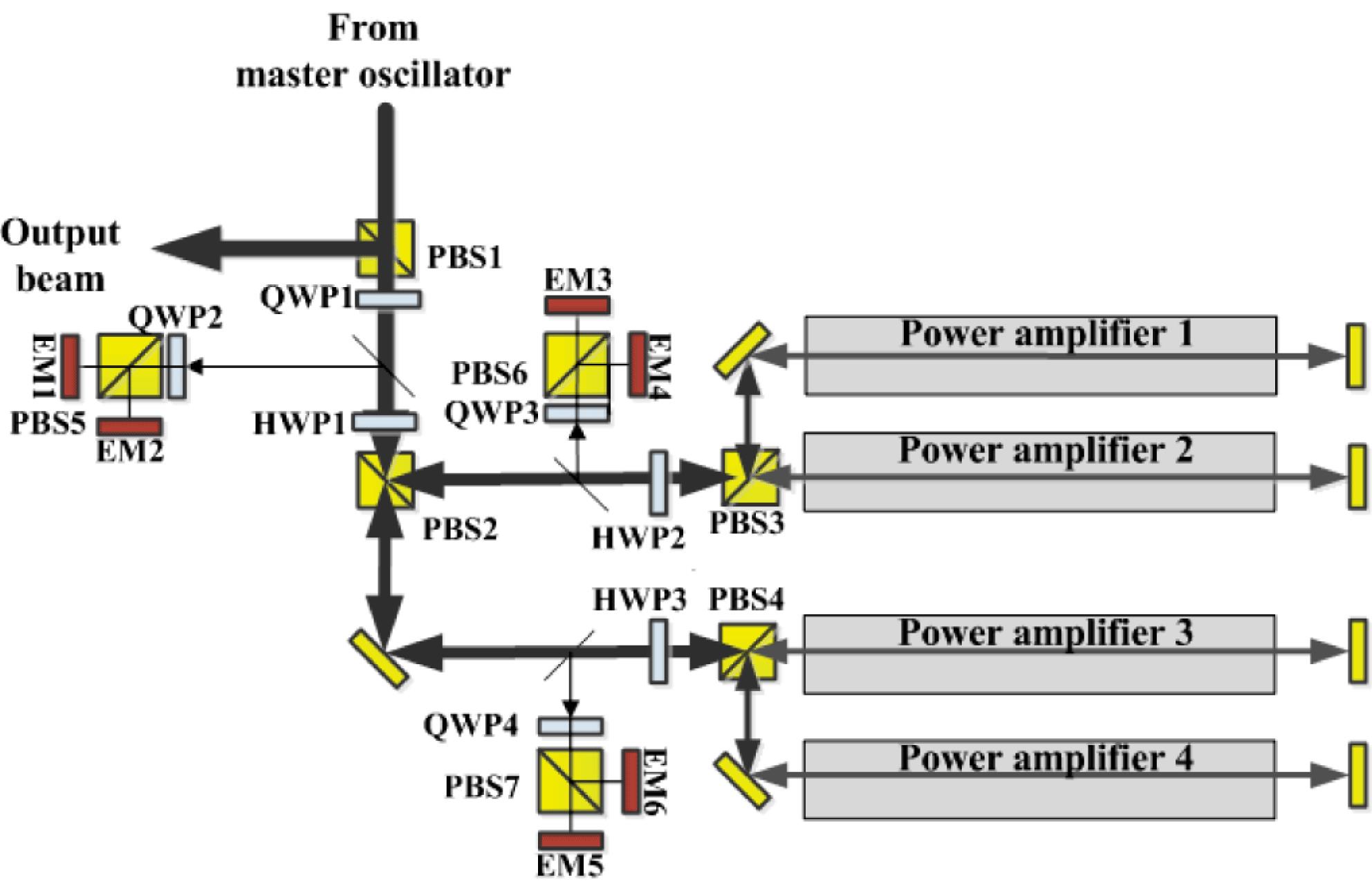
    Fig. 2. The MOPA beam combination laser with the amplitude combining method using PBSs: EM1–EM6, energy meters.
    MOPA beam combination laser with the amplitude combining method using a VBG.
    Fig. 3. MOPA beam combination laser with the amplitude combining method using a VBG.
    Types of SBS-PCM: (a) conventional SBS-PCM and (b) self-phase-locking SBS-PCM with PZT.
    Fig. 4. Types of SBS-PCM: (a) conventional SBS-PCM and (b) self-phase-locking SBS-PCM with PZT.
    Experimental setup of the self-phase-locked SBS-PCM: BS, beam splitter; W1 and W2, wedges; CM1 and CM2, concave mirrors.
    Fig. 5. Experimental setup of the self-phase-locked SBS-PCM: BS, beam splitter; W1 and W2, wedges; CM1 and CM2, concave mirrors.
    Experimental result of the self-phase-locked SBS-PCM. (a) A mosaic intensity pattern. It is generated by lining up one line of the intensity profile pattern recorded at each CCD image. (b) The measured relative phase. The standard deviation of the measured phase fluctuation is .
    Fig. 6. Experimental result of the self-phase-locked SBS-PCM. (a) A mosaic intensity pattern. It is generated by lining up one line of the intensity profile pattern recorded at each CCD image. (b) The measured relative phase. The standard deviation of the measured phase fluctuation is .
    Experimental setup of beam combination using an SBS-PCM and a feedback loop: M, mirror; W, wedged window; CM, concave mirror.
    Fig. 7. Experimental setup of beam combination using an SBS-PCM and a feedback loop: M, mirror; W, wedged window; CM, concave mirror.
    Experimental result of beam combination using an SBS-PCM and a feedback loop: (a) without operating the feedback loop and (b) with operation of the feedback loop.
    Fig. 8. Experimental result of beam combination using an SBS-PCM and a feedback loop: (a) without operating the feedback loop and (b) with operation of the feedback loop.
    Experimental setup of the four-beam combination using an SBS-PCM with the amplitude dividing method: , , , , , and , energy detectors; CM, concave mirror.
    Fig. 9. Experimental setup of the four-beam combination using an SBS-PCM with the amplitude dividing method: , , , , , and , energy detectors; CM, concave mirror.
    Measured phase fluctuation of four-beam combination using an SBS-PCM with the amplitude dividing method.
    Fig. 10. Measured phase fluctuation of four-beam combination using an SBS-PCM with the amplitude dividing method.
    Experimental setup of the four-beam combination amplifier using an SBS-PCM with the wavefront dividing method: HWP1 and HWP2, half-wave plates; BS, beam splitter; P1–P3, Prisms; M1–M3, mirrors; AMP1–AMP4, amplifiers; C1–C4, concave mirrors; W, wedge.
    Fig. 11. Experimental setup of the four-beam combination amplifier using an SBS-PCM with the wavefront dividing method: HWP1 and HWP2, half-wave plates; BS, beam splitter; P1–P3, Prisms; M1–M3, mirrors; AMP1–AMP4, amplifiers; C1–C4, concave mirrors; W, wedge.
    Measured phase fluctuation of the four-beam combination amplifier using an SBS-PCM with the wavefront dividing method.
    Fig. 12. Measured phase fluctuation of the four-beam combination amplifier using an SBS-PCM with the wavefront dividing method.
    Schematic diagram of the front end: FC/APC, fiber connector/angled physical contact; WDM, wavelength division multiplexor; BPF, bandpass filter; FC, fiber collimator; HR1 and HR2; high-reflectivity mirrors; A1 and A2, apertures.
    Fig. 13. Schematic diagram of the front end: FC/APC, fiber connector/angled physical contact; WDM, wavelength division multiplexor; BPF, bandpass filter; FC, fiber collimator; HR1 and HR2; high-reflectivity mirrors; A1 and A2, apertures.
    Schematic diagram of the pre-amplifier: RL1–RL5, relay lens pairs; PR1 and PR2, polarization rotators; HR, high-reflectivity mirror.
    Fig. 14. Schematic diagram of the pre-amplifier: RL1–RL5, relay lens pairs; PR1 and PR2, polarization rotators; HR, high-reflectivity mirror.
    Schematic diagram of the main amplifier: RL1–RL20, relay lens pairs; CM1–CM4, concave mirrors.
    Fig. 15. Schematic diagram of the main amplifier: RL1–RL20, relay lens pairs; CM1–CM4, concave mirrors.
    Schematic diagram of 2D laser processing using the Kumgang laser.
    Fig. 16. Schematic diagram of 2D laser processing using the Kumgang laser.
    Schematic diagram of the generation of a fs/ps laser using the Kumgang laser as a pump source: OPA1–OPA3, optical parametric amplifiers.
    Fig. 17. Schematic diagram of the generation of a fs/ps laser using the Kumgang laser as a pump source: OPA1–OPA3, optical parametric amplifiers.
    TypeSubtypeExamples of combining device
    IBCFrequency combiningDichroic mirror, prism, grating
    Side-by-side combiningLens array, mirror, wedge
    Polarization combiningPBS
    CBCWavefront combiningLens array, mirror, wedge
    Amplitude combiningPBS, beam splitter, grating
    Table 1. Beam combination methods.
    Wavefront combiningAmplitude combining
    Beam positions of combined beamsDifferent (tiled)Same (overlapping)
    ProsOutput power is always the sameHigh beam quality (same as input beams)
    ConsLower beam qualityOutput power is degraded when the phase control is imperfect
    Combining devicesLens array, mirror, wedge, etc.PBS, beam splitter, grating, etc.
    Table 2. CBC methods.
    Hong Jin Kong, Sangwoo Park, Seongwoo Cha, Heekyung Ahn, Hwihyeong Lee, Jungsuk Oh, Bong Ju Lee, Soungwoong Choi, and Jom Sool Kim. Conceptual design of the Kumgang laser: a high-power coherent beam combination laser using SC-SBS-PCMs towards a Dream laser[J]. High Power Laser Science and Engineering, 2015, 3(1): 010000e1
    Download Citation