
Hong Jin Kong, Sangwoo Park, Seongwoo Cha, Heekyung Ahn, Hwihyeong Lee, Jungsuk Oh, Bong Ju Lee, Soungwoong Choi, and Jom Sool Kim, "Conceptual design of the Kumgang laser: a high-power coherent beam combination laser using SC-SBS-PCMs towards a Dream laser," High Power Laser Sci. Eng. 3, 010000e1 (2015)
- High Power Laser Science and Engineering
- Vol. 3, Issue 1, 010000e1 (2015)
Abstract
1. Introduction
1.1. High-power coherent beam combination laser
Pulsed lasers with high power and a high repetition rate are greatly needed in many application fields, such as laser machining/annealing, neutron/proton generation, particle acceleration, laser fusion energy development, etc.[
Beam combination can contribute to the development of these high-power, high-repetition-rate lasers. There are two main lines of research in beam combination, namely beam combination of fiber lasers and beam combination of bulk lasers. There are many research groups in the field of fiber beam combination lasers, including the ICAN Program[ factor of a single-mode fiber laser is very good, so it is greatly advantageous to combine fiber lasers because only the piston errors need to be considered. Meanwhile, high-power bulk lasers tend to have lower beam quality than fiber lasers and it is very difficult to combine the beams. The main sources of a bulk laser’s low beam quality are the thermal lensing effect, pumping inhomogeneity and filamentation due to self-focusing.
To coherently combine bulk lasers, one should flatten the wavefront of the combining beams via active control or passive control. Active control utilizes an adaptive mirror[ factor[
Sign up for High Power Laser Science and Engineering TOC. Get the latest issue of High Power Laser Science and Engineering delivered right to you!Sign up now
Thus, we need to develop a scalable beam combination technique using an SBS-PCM that produces a phase-controllable SBS wave.
1.2. Beam combination laser using an SBS-PCM
H. J. Kong, the main author of this paper, proposed the simplest technique for controlling the phase of an SBS-PCM[
The feasibility of a beam combination laser using fluorocarbonate SBS-PCMs has been proved experimentally in the low power range of several W[
1.3. Kumgang laser
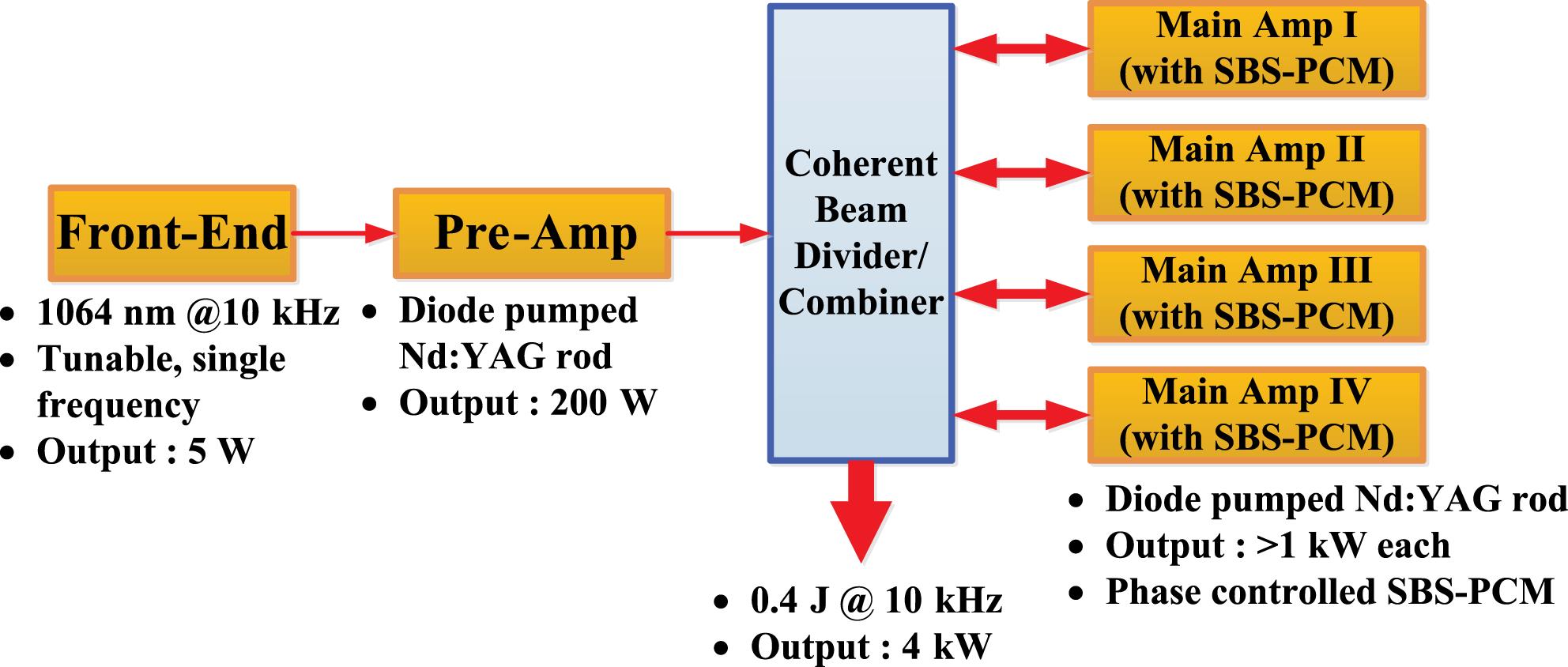
A project for a 4 kW beam combination laser system using SC-SBS-PCMs began in 2012 and the laser is called ‘Kumgang’, meaning diamond (or very important) in Korean. Four sub-beams, each with an energy of  pulse width and a repetition rate of 10 kHz, are coherently combined to produce an output beam with an energy of 0.4 J. It is a master oscillator power amplifier (MOPA) system and all of its pre- and main amplifiers are diode-pumped Nd:YAG amplifiers. The project will be completed by the end of 2015 and its first industrial application will be patterned 2D laser cutting of a printed circuit board (PCB) substrate.
| Type | Subtype | Examples of combining device |
|---|---|---|
| IBC | Frequency combining | Dichroic mirror, prism, grating |
| Side-by-side combining | Lens array, mirror, wedge | |
| Polarization combining | PBS | |
| CBC | Wavefront combining | Lens array, mirror, wedge |
| Amplitude combining | PBS, beam splitter, grating |
Table 1. Beam combination methods.
| Wavefront combining | Amplitude combining | |
|---|---|---|
| Beam positions of combined beams | Different (tiled) | Same (overlapping) |
| Pros | Output power is always the same | High beam quality (same as input beams) |
| Cons | Lower beam quality | Output power is degraded when the phase control is imperfect |
| Combining devices | Lens array, mirror, wedge, etc. | PBS, beam splitter, grating, etc. |
Table 2. CBC methods.
Figure
In Section
2. CBC laser
2.1. Methods of beam combination
There are several methods of constructing beam combination lasers[
Table
The other two methods are monochromatic. The side-by-side beam combination method combines the beams blindly, only aligning them side by side, and does not consider their relative phases. The radiance does not scale with the number of combining beams and the focused beam pattern is irregular and random. This type of beam combination is only applicable when only the power of the beam is important. It is of no use for most applications where the focused beam intensity is critical.
The last type of IBC is the polarization combining method. Two beams with the same frequency and opposite polarization can be combined using a PBS or other polarization optics. Since the relative phase between the two beams is random, the output polarization is random and undetermined. Therefore, one cannot combine more than two beams using this method.
There are two types of CBC as shown in Table
The other method of CBC is amplitude combination. It combines the beams to have the same position and the same direction. In this case, control of the relative phases is very important and it directly affects the output power by interference. The most beneficial property of amplitude beam combination is that the beam quality remains unchanged compared with the combining beams. This is because the shape of the combining beams is the same as that of the combined beam. On the other hand, the output power of the amplitude combined beam fluctuates as the piston phases deviate from zero. When all the piston phases are zero, the output power is maximal and is the same as the sum of the combining beams. Otherwise, the output power is lower than the sum. A beam splitter can combine two beams with the same polarization and power. The output power of the beam splitter is dependent on the phase difference between the two beams, and when the difference is zero, the output power is twice the power of the combining beams. One can combine  beams by cascading the process
  times. Amplitude beam combination using a PBS is a special case of beam splitting. Using two beams with opposite polarizations, the output power of the PBS is the sum of the two beams, but the polarization of the output is random and typically elliptical. By controlling the relative phase between the two beams, the output polarization is fixed to a known state and the combined output beam can be combined with another beam by the same method. A grating can also coherently combine the beams. This is done either by combining several high-order beams into a zeroth-order beam, or by combining several first-order beams of co-existing gratings into a common zeroth-order beam. In any case, the output power can be reduced without controlling the relative phases.
In beam combination using MOPA systems, the laser beam from the master oscillator is divided into several beams. After the amplification from the power amplifier, they are combined to make the output beam. Typically, the beam dividing optics and the beam combining optics are the same. When using the wavefront dividing method, division of the beam into sub-beams with sharp edges induces severe diffraction with very dangerous intensity spikes. To eliminate them, sophisticated methods like serrated apertures are needed and, therefore, the power of the divided beam is typically lower than that of the amplitude dividing method. Considering this limitation and other factors, the amplitude dividing/combining method will be employed for the Kumgang laser. Two possible methods of amplitude combination are presented below.
2.2. Amplitude beam combination using a PBS
Figure  and the output beam is reflected on PBS1. PBS2 divides the input beam into two beams. With a proper angle of half-wave plate (HWP1), PBS2 can divide the beam into two beams with the same power. Likewise, HWP2, PBS3, HWP3 and PBS4 divide the two beams into four beams. Four power amplifier chains amplify each beam in a double-pass configuration. To measure the relative phases between the beams, at each combining stage, a small portion of the combined beam is directed towards a measurement stage. Each measurement stage consists of one QWP, one PBS and two energy meters. By measuring the energy on the two energy meters, the relative phase between two combining beams can be calculated[
2.3. Amplitude beam combination using a VBG
Figure
3. CBC laser using an SBS-PCM
3.1. SBS-PCM
The SBS-PCM is one type of PCM. The SBS phenomenon can be explained as follows[
The main amplifiers in an MOPA beam combination laser are not exactly the same. Therefore, the wavefronts of the divided beams are distorted in different ways. Unless these distortions are compensated for, CBC cannot be achieved. By using a double-pass amplification scheme and utilizing the SBS-PCM as a back reflector of the main amplifier, the wavefronts are restored after the second pass due to the phase conjugation property of the SBS. In this case, CBC is possible if the piston phases are controlled. Unfortunately, since the reflected beam from the SBS-PCM originates from random thermal noise, the phases of the reflections are random, and the piston phases cannot be controlled.
3.2. Self-phase control of an SBS-PCM
Figure
3.3. Experimental results for the beam combination laser using a SC-SBS-PCM
The principles of the SC-SBS-PCM were experimentally verified in 2005[
Figure
Figure  .
.
Figure  . After reflection from the SC-SBS-PCM and the second pass of the FR, the polarization of the beam is now perpendicular to the input beam and the combined beam is reflected at the PBS. The method for measuring the relative phase is the same as in Figure
Figure  .
.
Figure  , PZT1 is operated to compensate for the phase difference. Likewise, using the measured phase between beam 3 and beam 4
  , PZT2 is operated. From the measured phase between the combined beam of 1&2 and the combined beam of 3&4
  both PZT2 and PZT3 are operated to compensate for the path length difference.
Figure  ,
,  and
and  are all stabilized and have standard deviations of
  ,
,  and
and  , respectively. The output energy is also stabilized to 6.16% of the average in standard deviation.
Figure  and minimizes the thermal depolarization of the amplifier. At the end of each beam line, SC-SBS-PCMs reflect the beam. Inside one of the beam lines (beam 1), a wedge is installed to make a reference beam (beam 0). The reference beam is expanded and makes an interference pattern with the output beam. From the interference pattern, the relative phases between the reference beam and the four beams can be calculated (
 ,
,  ,
,  and
and  ).
).
Figure  is the interference between beam 1 and the reference beam. Both beams are from the same SBS-PCM and
  is stabilized to
  .
.  ,
,  and
and  are the interferences between different beam lines, and they are all stabilized and have standard deviations of
  ,
,  and
and  , respectively. The input energy of the beam after the beam aperture is
  and the output energy of the amplified combined beam is
  .
.
4. Kumgang laser
The Kumgang laser, which is now under construction, will be a high-power, high-repetition-rate beam combination laser that uses SC-SBS-PCMs. Four sub-beams, each with a power of 1 kW, are combined to make a 10 kHz/10 ns laser beam with a pulse energy of 400 mJ. Therefore, the total output power is 4 kW. The research on the Kumgang laser and its application started in 2012 and will be completed by the end of 2015.
4.1. Front-end subsystem
Figure
The Nd:YAG regenerative amplifier amplifies the beam further. The beam passes through FR1, HWP1 and PBS. The PBS acts as an output coupler. Next, the FR2 rotates the polarization of the beam by  and HWP2 reverses the effect of FR2. When the beam is injected into the regenerative amplifier through the thin-film polarizer (TFP1), the Pockels cell (PC) is in the ‘open’ state and does not change the polarization of the injected beam. The QWP rotates the polarization and the beam is reflected at TFP1. While the beam is being amplified at the gain module (GM) for the first time, the PC changes to a ‘closed’ state and reverses the effect of the QWP. Now the beam is trapped in the regenerative amplifier and passes between the high-reflectivity mirrors HR1 and HR2 many times. After sufficient amplification, the PC changes back to the ‘open’ state and the beam leaves the regenerative amplifier. The net effect on the polarization of the returning beam by FR2 and HWP2 is a
  rotation and the beam is reflected at the PBS. The average output power of the front-end subsystem is 5 W (0.5 mJ/10 ns/10 kHz).
4.2. Pre-amplifier subsystem
The pre-amplifier subsystem is depicted in Figure  between two GMs. After passing through the FR twice, the beam is amplified again in the second pass. Relay lens pairs relay the image of the beam from the input position of the pre-amplifier to GM1, to GM2 and to the high-reflectivity mirror and back.
Pre-amplifier stage II has another two GMs with the same specifications as stage I. In this case, the beam passes through the amplifiers only once. An image of the beam at the output position of pre-amplifier stage I is relayed to GM3 and to GM4. The average output power of the pre-amplifier subsystem is 200 W (20 mJ/10 ns/10 kHz).
4.3. Main amplifier subsystem
Figure  after the first and the third GM to minimize thermal depolarization. Image relaying lenses relay the beam image from the output position of the pre-amplifier to the GMs one by one, and to the SBS-PCM and back.
After passing through the FR, the beam is reflected from the SC-SBS-PCM. The SC-SBS-PCM generates a phase conjugated wave, so any wavefront distortion in the first pass is compensated for automatically in the second pass. After amplification, each sub-beam has a power of 1 kW (100 mJ/10 ns/10 kHz), and four sub-beams are combined at the beam divider/combiner. A phase measurement device measures the relative phases between the four sub-beams. The exact nature of the phase measurement device needs to be studied and is dependent on the beam divider/combiner. Three of the four concave mirrors in the SC-SBS-PCMs are attached to the PZT. The relative phases are compensated for by the movement of these PZTs. The output beam of the Kumgang laser will be a 4 kW, 10 kHz pulse train. Each pulse will have a pulse width of 10 ns and an energy of 400 mJ.
4.4. Applications of the Kumgang laser
There are two distinct pulse width ranges among short-pulse lasers. For applications requiring high power and high peak power, ns pulsed lasers are suitable. The Kumgang laser falls in this category. On the other hand, for applications requiring high power and extremely high peak power, ps and/or fs pulsed lasers are suitable. This category will be discussed in Section
There are many applications for high-power ns pulsed lasers like the Kumgang laser. For defense, high-power lasers with powers of over 100 kW can be effective weapons for intercepting missiles, rockets and mortar shells with soft-kill/hard-kill methods. Further, using a neutron beam or x-ray generated by a laser, explosives and nuclear materials can be detected early. For medical applications, proton beams generated by lasers can be directed to cancer cells deep within the body and kill them while minimizing collateral damage. Neutron and proton beams can also generate radioactive isotopes that can be used in various fields including medical imaging. For manufacturing, laser peening technology can harden the surface of a material more than conventional peening. On the other hand, extreme UV (EUV) light can be generated with high brightness by high-power ns lasers. Using this EUV light, the linewidth of the lithography used in the semiconductor industry can be reduced severalfold. The laser fusion driver of inertial confinement fusion is also of great interest. To cost-effectively generate electricity, the laser fusion driver should operate with a repetition rate of at least 0.1 Hz and an energy of at least several kJ, and the whole fusion power plant will require one to two hundred such laser drivers.
The Kumgang laser aims for 2D cutting of a PCB substrate using holography. Figure
5. High-power fs/ps lasers generated by the Kumgang laser
5.1. Optical parametric chirped-pulse amplification
Since the peak power of fs/ps lasers is very high compared with ns lasers, chirped-pulse amplification (CPA) is usually employed to amplify fs/ps lasers to high power. It stretches the pulse width to a nanosecond range by dispersive optics. After amplification of the stretched and low-peak-power pulses, a compressor reverses the effect of the stretcher, creating a fs/ps pulse with higher energy. Due to many problems regarding the amplifying medium like thermal effects, amplified spontaneous emission and parasitic lasing, CPA has its limitations.
Optical parametric CPA (OPCPA) is a novel technology for building high-power fs/ps lasers. Instead of using a laser medium with a large amplification linewidth like CPA, a nonlinear crystal amplifies the chirped beam by an optical parametric amplification (OPA) process. Since absorption and emission do not occur in the crystal, the thermal load is very low and the problems originating from spontaneous emission disappear. For efficient OPA to occur, the pump beam of the OPA should have a comparable pulse width to the amplifying beam. The Kumgang laser, a high-power, high-repetition-rate ns pulsed laser, will be a good pump beam for OPCPA of fs/ps lasers with a pulse energy of several tens of mJ and a repetition rate of 10 kHz.
Figure
5.2. Applications for a high-power, high-repetition-rate fs/ps laser
High-power, high-repetition-rate fs/ps lasers have many applications. The extremely high peak power and intensity enable various new fields. First of all, a high-brightness x-ray can be generated from the high-power fs/ps laser by various methods, including high-harmonic generation. High-brightness x-rays can probe very small and very fast processes in chemistry, materials science and medical science. On the other hand, a high-power fs/ps laser can generate a gamma-ray by Compton scattering. The properties of the laser-based gamma-ray can be adjusted easily and it is very useful in nuclear science. Furthermore, laser wakefield acceleration of protons and other ions has applications in cancer therapy and in the field of materials science. In addition, these accelerated ions can generate high-energy and high-density neutron beams by nuclear reaction. Since the neutron has no charge, it can penetrate matter at a long distance. Moreover, depending on the energy of the neutron beam, it can examine suspicious baggage non-destructively or treat cancer. Finally, the high electric field itself can probe linear and nonlinear relativistic effects in matter and in the vacuum.
6. Summary
Beam combination of lasers can contribute to the development of high-power, high-repetition-rate lasers. The SC-SBS-PCM used in a double-pass amplifier can compensate for the distorted wavefront from the amplifiers. Since the SC-SBS-PCM has a very simple and independently configured optical scheme, scalable beam combination of bulk pulsed lasers is possible.
An SC-SBS-PCM was demonstrated several times at the academic low power level of several watts. Using PZTs, the path length fluctuation between the beam lines is controlled. Four beam combination lasers using both the wavefront dividing method and the amplitude dividing method were proved experimentally.
The Kumgang laser, a beam combination laser combining four 1 kW beams to make 4 kW output (400 mJ/10 ns/10 kHz), is now under development to test whether this scheme is appropriate for high-power lasers. The Kumgang laser has four subsystems. The front-end subsystem generates the seed beam using a LD oscillator and an AOM. It amplifies the seed beam to 5 W (0.5 mJ/10 ns/10 kHz) using a fiber amplifier and a regenerative amplifier. The pre-amplifier subsystem amplifies the beam further to 200 W (20 mJ/10 ns/10 kHz) using Nd:YAG amplifiers. After dividing it into four sub-beams, the main amplifier amplifies each beam to 1 kW (100 mJ/10 ns/10 kHz) in a double-pass configuration. The wavefront combining method using a VHG or a PBS will be employed for the Kumgang laser.
There are many applications for high-power, high-repetition-rate lasers. One of the possibilities is to use a ns pulsed laser like the Kumgang as a pump source for ps/fs pulse generation by OPCPA. If the Kumgang laser functions successfully, it will be the most important step towards a Dream laser with ns, ps or fs pulse width, which is, a hypothetical laser with unlimited power and a high repetition rate.
References
[1] F. Bachmann. Appl. Surf. Sci., 208, 125(2003).
[4] G. H. Miller, E. I. Moses, C. R. Wuest. Opt. Eng., 43, 2841(2004).
[5] X. Wang, P. Zhou, Y. Ma, J. Leng, X. Xu, Z. Liu. Opt. Lett., 36, 3121(2011).
[8] G. Mourou, B. Brocklesby, T. Tajima, J. Limpert. Nat. Photonics, 7, 258(2013).
[9] R. L. Farrow, D. A. V. Kline, G. R. Hadley, A. V. Smith. Opt. Lett., 31, 3423(2006).
[10] Tso Yee Fan. IEEE J. Sel. Top. Quant. Electron., 11, 567(2005).
[12] R. A. Fisher. Optical Phase Conjugation(1983).
[13] B. Y. Zel’dovich, V. I. Popovichev, V. V. Ragulsky, F. S. Faizullov. Sov. Phys. JETP, 15, 109(1972).
[17] D. A. Rockwell, C. R. Giuliano. Opt. Lett., 11, 147(1986).
[18] M. Valley, G. Lombardi, R. Aprahamian. J. Opt. Soc. Am. B, 3, 1492(1986).
[19] N. F. Andreev, O. V. Palashov, G. A. Pasmanik, E. A. Khazanov. Quant. Electron., 27, 565(1997).
[20] H. J. Kong, S. K. Lee, D. W. Lee. Laser Part. Beams, 23, 107(2005).
[21] H. J. Kong, S. K. Lee, D. W. Lee. Laser Part. Beams, 23, 55(2005).
[22] W. L. J. Hasi, Z. W. Lu, S. Gong, S. J. Liu, Q. Li, W. M. He. Appl. Opt., 47, 1010(2008).
[23] H. J. Kong, S. K. Lee, D. W. Lee, H. Guo. Appl. Phys. Lett., 86(2005).
[24] S. K. Lee, H. J. Kong, M. Nakatsuka. Appl. Phys. Lett., 87(2005).
[25] H. J. Kong, J. W. Yoon, J. S. Shin, D. H. Beak, B. J. Lee. Laser Part. Beams, 24, 519(2006).
[26] H. J. Kong, J. W. Yoon, J. S. Shin, D. H. Beak. Appl. Phys. Lett., 92(2008).
[27] J. W. Yoon, J. S. Shin, D. H. Beak, H. J. Kong. Opt. Commun., 282, 1000(2009).
[28] H. J. Kong, J. S. Shin, J. W. Yoon, D. H. Beak. Laser Part. Beams, 27, 179(2009).
[29] H. J. Kong, J. S. Shin, J. W. Yoon, D. H. Beak. Nucl. Fusion, 49(2009).
[30] J. S. Shin, S. Park, H. J. Kong, J. W. Yoon. Appl. Phys. Lett., 96(2010).
[31] H. J. Kong, J. S. Shin, S. Park. J. Korean Phys. Soc., 57, 316(2010).
[32] S. K. Case. J. Opt. Soc. Am., 65, 724(1975).
[34] Y. R. Shen. The Principles of Nonlinear Optics(1984).
[35] S. Afshaarvahid, V. Devrelis, J. Munch. Phys. Rev. A, 57, 3961(1998).
[36] H. J. Eichler, O. Mehl. J. Nonlinear Opt. Phys., 10, 43(2001).
[37] R. Menzel, H. J. Eichler. Phys. Rev. A, 46, 7139(1992).


Set citation alerts for the article
Please enter your email address

© Copyright 2018-2021 | Chinese Laser Press. All Rights Reserved 沪ICP备15018463号-20