• Photonics Research
  • Vol. 11, Issue 4, 631 (2023)
Huanhao Li1、2、†, Zhipeng Yu1、2、†, Qi Zhao1、2、†, Yunqi Luo3, Shengfu Cheng1、2, Tianting Zhong1、2, Chi Man Woo1、2, Honglin Liu1、4, Lihong V. Wang5、7、*, Yuanjin Zheng3、8、*, and Puxiang Lai1、2、6、9、*
Author Affiliations
  • 1Department of Biomedical Engineering, Hong Kong Polytechnic University, Hong Kong, China
  • 2Hong Kong Polytechnic University Shenzhen Research Institute, Shenzhen 518063, China
  • 3School of Electrical and Electronics Engineering, Nanyang Technological University, Singapore 639798, Singapore
  • 4Key Laboratory for Quantum Optics, Shanghai Institute of Optics and Fine Mechanics, Chinese Academy of Sciences, Shanghai 201800, China
  • 5Caltech Optical Imaging Laboratory, Andrew and Peggy Cherng Department of Medical Engineering, California Institute of Technology, Pasadena, California 91125, USA
  • 6Photonics Research Institute, Hong Kong Polytechnic University, Hong Kong, China
  • 7e-mail: LVW@caltech.edu
  • 8e-mail: yjzheng@ntu.edu.sg
  • 9e-mail: puxiang.lai@polyu.edu.hk
  • show less
    DOI: 10.1364/PRJ.472512 Cite this Article Set citation alerts
    Huanhao Li, Zhipeng Yu, Qi Zhao, Yunqi Luo, Shengfu Cheng, Tianting Zhong, Chi Man Woo, Honglin Liu, Lihong V. Wang, Yuanjin Zheng, Puxiang Lai. Learning-based super-resolution interpolation for sub-Nyquist sampled laser speckles[J]. Photonics Research, 2023, 11(4): 631 Copy Citation Text show less
    Conceptional diagram of speckle collection, deep-learning-based speckle super-resolution interpolation processing and information recovery. Phase objects are displayed on the SLM, which is illuminated by an expanded continuous coherent laser beam (λ=532 nm). Speckle patterns behind the scattering medium are down sampled for rapid recording, transmission, and storage, or enhanced SNR. Inevitably, intrinsic correlations among speckle grains and hence the encoded information are irreversibly impaired. In signal processing, the down-sampled speckles are interpolated via a deep-learning based super-resolution framework to reverse the “irreversibility” and retrace with high-fidelity the speckle comprehensive morphology and finally the encoded object information.
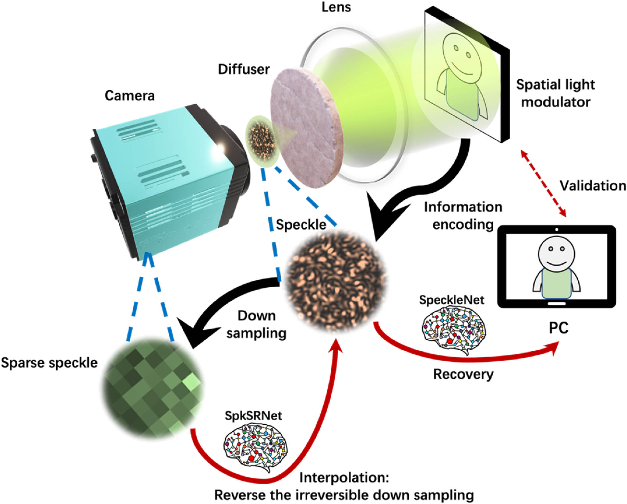
    Fig. 1. Conceptional diagram of speckle collection, deep-learning-based speckle super-resolution interpolation processing and information recovery. Phase objects are displayed on the SLM, which is illuminated by an expanded continuous coherent laser beam (λ=532  nm). Speckle patterns behind the scattering medium are down sampled for rapid recording, transmission, and storage, or enhanced SNR. Inevitably, intrinsic correlations among speckle grains and hence the encoded information are irreversibly impaired. In signal processing, the down-sampled speckles are interpolated via a deep-learning based super-resolution framework to reverse the “irreversibility” and retrace with high-fidelity the speckle comprehensive morphology and finally the encoded object information.
    Architecture of SpkSRNet is the combination of ResNeXt and PixelShuffle layers. nd0-sampled speckles with the dimension of d×d (d=252/n) are input into the SpkSRNet for speckle super-resolution (i.e., interpolation) processing (n=4, 8, 12, 18, 21, 28), with d0-sampled speckles (i.e., the original speckles with the dimension of 252×252) as the target. For example, when the down-sampling factor (n) is 12, the network is called 12d0-trained SpkSRNet, whose input dimension is 21×21 and output dimension is 252×252.
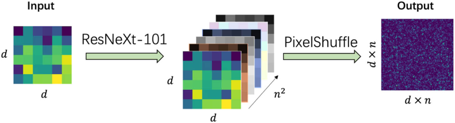
    Fig. 2. Architecture of SpkSRNet is the combination of ResNeXt and PixelShuffle layers. nd0-sampled speckles with the dimension of d×d(d=252/n) are input into the SpkSRNet for speckle super-resolution (i.e., interpolation) processing (n=4, 8, 12, 18, 21, 28), with d0-sampled speckles (i.e., the original speckles with the dimension of 252×252) as the target. For example, when the down-sampling factor (n) is 12, the network is called 12d0-trained SpkSRNet, whose input dimension is 21×21 and output dimension is 252×252.
    Sampling effect for information recovery. (a) Representative speckle patterns with different sampling factors. From Columns I to VII, speckles are sampled with sampling factors of 1, 4, 8, 12, 18, 21, and 28, respectively. (b) Reconstructed images via the corresponding SpeckleNet, with the PCC and MSE information with respect to the ground truth (c). (d) PCC and MSE of the reconstructed face images with respect to the ground truth as a function of the down-sampling factor (n). The solid line and the colored region represent the mean value and the standard deviation, respectively, among the 2000 test samples. The ground truth image (c) is reproduced under terms of the Public Domain Mark 1.0 license, and captured by DOCB Bengaluru on 2017-08-06, Flickr (https://www.flickr.com/photos/docb400/35592623433/). The original image is cropped and converted to gray scale. Images in (b) are generated via the deep learning output based on the transformation of (c) for signal processing purpose.
    Fig. 3. Sampling effect for information recovery. (a) Representative speckle patterns with different sampling factors. From Columns I to VII, speckles are sampled with sampling factors of 1, 4, 8, 12, 18, 21, and 28, respectively. (b) Reconstructed images via the corresponding SpeckleNet, with the PCC and MSE information with respect to the ground truth (c). (d) PCC and MSE of the reconstructed face images with respect to the ground truth as a function of the down-sampling factor (n). The solid line and the colored region represent the mean value and the standard deviation, respectively, among the 2000 test samples. The ground truth image (c) is reproduced under terms of the Public Domain Mark 1.0 license, and captured by DOCB Bengaluru on 2017-08-06, Flickr (https://www.flickr.com/photos/docb400/35592623433/). The original image is cropped and converted to gray scale. Images in (b) are generated via the deep learning output based on the transformation of (c) for signal processing purpose.
    Speckle interpolation based on classic methods and the corresponding learning-based imaging reconstruction. (a) Down-sampled speckle patterns with a sampling factor from 4 to 28. (b1) and (c1) are the up-sampled (i.e., interpolated) speckle patterns through bicubic and bilinear interpolations, respectively. (b2) and (c2) are the reconstructed images by feeding (b1) and (c1) are into the SpeckleNet. (d) d0-sampled speckles. The ground truth image (e) is reproduced under terms of the Public Domain Mark 1.0 license, and captured by DOCB Bengaluru on 2017-08-06, Flickr (https://www.flickr.com/photos/docb400/35592623433/). The original image is cropped and converted to gray scale. Images in (b2) and (c2) are generated via the deep learning output based on the transformation of (e) for signal processing purpose.
    Fig. 4. Speckle interpolation based on classic methods and the corresponding learning-based imaging reconstruction. (a) Down-sampled speckle patterns with a sampling factor from 4 to 28. (b1) and (c1) are the up-sampled (i.e., interpolated) speckle patterns through bicubic and bilinear interpolations, respectively. (b2) and (c2) are the reconstructed images by feeding (b1) and (c1) are into the SpeckleNet. (d) d0-sampled speckles. The ground truth image (e) is reproduced under terms of the Public Domain Mark 1.0 license, and captured by DOCB Bengaluru on 2017-08-06, Flickr (https://www.flickr.com/photos/docb400/35592623433/). The original image is cropped and converted to gray scale. Images in (b2) and (c2) are generated via the deep learning output based on the transformation of (e) for signal processing purpose.
    Learning-based super-resolution interpolation and imaging reconstruction. (a) Speckle patterns with a sampling factor from 1 to 28. (b) The corresponding interpolated speckles via SpkSRNet for down-sampled speckle patterns. The insets are the PCC (MSE) with respect to the ground truth speckle pattern in Column I of panel (a). (c) The corresponding reconstructed images via SpeckleNet for d0-sampled and interpolated speckles. The insets are the PCC (MSE) with respect to the ground truth face image [Fig. 3(c)]. Images in (c) are generated via deep learning output based on the transformation of Fig. 3(c), which is reproduced under terms of the Public Domain Mark 1.0 license, and captured by DOCB Bengaluru on 2017-08-06, Flickr (https://www.flickr.com/photos/docb400/35592623433/).
    Fig. 5. Learning-based super-resolution interpolation and imaging reconstruction. (a) Speckle patterns with a sampling factor from 1 to 28. (b) The corresponding interpolated speckles via SpkSRNet for down-sampled speckle patterns. The insets are the PCC (MSE) with respect to the ground truth speckle pattern in Column I of panel (a). (c) The corresponding reconstructed images via SpeckleNet for d0-sampled and interpolated speckles. The insets are the PCC (MSE) with respect to the ground truth face image [Fig. 3(c)]. Images in (c) are generated via deep learning output based on the transformation of Fig. 3(c), which is reproduced under terms of the Public Domain Mark 1.0 license, and captured by DOCB Bengaluru on 2017-08-06, Flickr (https://www.flickr.com/photos/docb400/35592623433/).
    Performance analysis of speckle interpolation and image reconstruction. (a)–(c) The PCC (a), SSIM (b), and MSE (c) between the interpolated speckles of interest and the original speckles (d0-sampled). (d)–(f) The PCC (d), SSIM (e), and MSE (f) between the corresponding reconstructed images and the target human face. The solid lines and the shadowed regions represent the mean value and the standard deviation, respectively, from the 2000 testing samples.
    Fig. 6. Performance analysis of speckle interpolation and image reconstruction. (a)–(c) The PCC (a), SSIM (b), and MSE (c) between the interpolated speckles of interest and the original speckles (d0-sampled). (d)–(f) The PCC (d), SSIM (e), and MSE (f) between the corresponding reconstructed images and the target human face. The solid lines and the shadowed regions represent the mean value and the standard deviation, respectively, from the 2000 testing samples.
    Learning-based speckle interpolation and information recovery under low-light condition. (a1) Speckles collected in low-light condition (optical power=2.4 μW and SNR=0.04). (a2) Down-sampled speckles (SNR=0.28) through combining 12×12 pixels in (a1). (a3) The learning-based interpolated speckles by feeding (a2) into the SpkSRNet trained by the 12d0-sampled speckles. (b1)–(b3) are the reconstructed images of (a1)–(a3), respectively, via the SpeckleNet. The red downward arrows represent learning-based image reconstruction. The image in (b3) is generated via the deep learning output based on the transformation of Fig. 3(c), which is reproduced under terms of the Public Domain Mark 1.0 license, and captured by DOCB Bengaluru on 2017-08-06, Flickr (https://www.flickr.com/photos/docb400/35592623433/).
    Fig. 7. Learning-based speckle interpolation and information recovery under low-light condition. (a1) Speckles collected in low-light condition (opticalpower=2.4  μW and SNR=0.04). (a2) Down-sampled speckles (SNR=0.28) through combining 12×12 pixels in (a1). (a3) The learning-based interpolated speckles by feeding (a2) into the SpkSRNet trained by the 12d0-sampled speckles. (b1)–(b3) are the reconstructed images of (a1)–(a3), respectively, via the SpeckleNet. The red downward arrows represent learning-based image reconstruction. The image in (b3) is generated via the deep learning output based on the transformation of Fig. 3(c), which is reproduced under terms of the Public Domain Mark 1.0 license, and captured by DOCB Bengaluru on 2017-08-06, Flickr (https://www.flickr.com/photos/docb400/35592623433/).
    Speckle interpolation and the corresponding learning-based imaging reconstruction. (a1) The original speckles generated with the image (a2). (b1) Down-sampled speckle patterns with sampling factors from 4 to 28. (c1), (d1), and (e1) are the up-sampled (i.e., interpolated) speckle patterns through bilinear, bicubic, and SpkSRNet methods, respectively. (b2), (c2), (d2), and (e2) are the reconstructed images by feeding (b1), (c1), (d1), and (e1) into the SpeckleNet. The ground truth image (a2) is reproduced under terms of the Public Domain Mark 1.0 license, and captured by Lionel AZRIA on 2018-05-15, Flickr (https://www.flickr.com/photos/157170122@N07/28252868748/). The original image is cropped and converted to gray scale. Images in (b2), (c2), (d2) and (e2) are generated via the deep learning output based on the transformation of (a2) for signal processing purpose.
    Fig. 8. Speckle interpolation and the corresponding learning-based imaging reconstruction. (a1) The original speckles generated with the image (a2). (b1) Down-sampled speckle patterns with sampling factors from 4 to 28. (c1), (d1), and (e1) are the up-sampled (i.e., interpolated) speckle patterns through bilinear, bicubic, and SpkSRNet methods, respectively. (b2), (c2), (d2), and (e2) are the reconstructed images by feeding (b1), (c1), (d1), and (e1) into the SpeckleNet. The ground truth image (a2) is reproduced under terms of the Public Domain Mark 1.0 license, and captured by Lionel AZRIA on 2018-05-15, Flickr (https://www.flickr.com/photos/157170122@N07/28252868748/). The original image is cropped and converted to gray scale. Images in (b2), (c2), (d2) and (e2) are generated via the deep learning output based on the transformation of (a2) for signal processing purpose.
    Learning-based speckle interpolation and information recovery under low-light condition. (a1) Speckles collected in low-light condition (optical power=2.4 μW and SNR=0.04). (a2) Down-sampled speckles (SNR=0.28) through combining 12×12 pixels in (a1). (a3) The learning-based interpolated speckles by feeding (a2) into the SpkSRNet trained by the 12d0-sampled speckles. (b1)–(b3) are the reconstructed images of (a1)–(a3), respectively, via the SpeckleNet. The red downward arrows represent learning-based image reconstruction. The image in (b3) is generated via the deep learning output based on the transformation of Fig. 8(a2), which is reproduced under terms of the Public Domain Mark 1.0 license, and captured by Lionel AZRIA on 2018-05-15, Flickr (https://www.flickr.com/photos/157170122@N07/28252868748/).
    Fig. 9. Learning-based speckle interpolation and information recovery under low-light condition. (a1) Speckles collected in low-light condition (opticalpower=2.4  μW and SNR=0.04). (a2) Down-sampled speckles (SNR=0.28) through combining 12×12 pixels in (a1). (a3) The learning-based interpolated speckles by feeding (a2) into the SpkSRNet trained by the 12d0-sampled speckles. (b1)–(b3) are the reconstructed images of (a1)–(a3), respectively, via the SpeckleNet. The red downward arrows represent learning-based image reconstruction. The image in (b3) is generated via the deep learning output based on the transformation of Fig. 8(a2), which is reproduced under terms of the Public Domain Mark 1.0 license, and captured by Lionel AZRIA on 2018-05-15, Flickr (https://www.flickr.com/photos/157170122@N07/28252868748/).
    Speckle interpolation and the corresponding learning-based imaging reconstruction. (a1) Original speckles generated with the image (a2). (b1) Down-sampled speckle patterns with sampling factors from 4 to 28. (c1), (d1), and (e1) are the up-sampled (i.e., interpolated) speckle patterns through bilinear, bicubic, and SpkSRNet methods, respectively. (b2), (c2), (d2), and (e2) are the reconstructed images by feeding (b1), (c1), (d1), and (e1) into the SpeckleNet. The ground truth image (a2) is reproduced under terms of the Public Domain Mark 1.0 license, and captured by Kya-Lynn on 2018-06-05, Flickr (https://www.flickr.com/photos/141074874@N05/41849168674/). The original image is cropped and converted to gray scale. Images in (b2), (c2), (d2), and (e2) are generated via the deep learning output based on the transformation of (a2) for signal processing purpose.
    Fig. 10. Speckle interpolation and the corresponding learning-based imaging reconstruction. (a1) Original speckles generated with the image (a2). (b1) Down-sampled speckle patterns with sampling factors from 4 to 28. (c1), (d1), and (e1) are the up-sampled (i.e., interpolated) speckle patterns through bilinear, bicubic, and SpkSRNet methods, respectively. (b2), (c2), (d2), and (e2) are the reconstructed images by feeding (b1), (c1), (d1), and (e1) into the SpeckleNet. The ground truth image (a2) is reproduced under terms of the Public Domain Mark 1.0 license, and captured by Kya-Lynn on 2018-06-05, Flickr (https://www.flickr.com/photos/141074874@N05/41849168674/). The original image is cropped and converted to gray scale. Images in (b2), (c2), (d2), and (e2) are generated via the deep learning output based on the transformation of (a2) for signal processing purpose.
    Learning-based speckle interpolation and information recovery under low-light condition. (a1) Speckles collected in low-light condition (optical power=2.4 μW and SNR=0.04). (a2) Down-sampled speckles (SNR=0.28) through combining 12×12 pixels in (a1). (a3) The learning-based interpolated speckles by feeding (a2) into the SpkSRNet trained by the 12d0-sampled speckles. (b1)–(b3) are the reconstructed images of (a1)–(a3), respectively, via the SpeckleNet. The red downward arrows represent learning-based image reconstruction. The image in (b3) is generated via the deep learning output based on the transformation of Fig. 10(a2), which is reproduced under terms of the Public Domain Mark 1.0 license, and captured by Kya-Lynn on 2018-06-05, Flickr (https://www.flickr.com/photos/141074874@N05/41849168674/).
    Fig. 11. Learning-based speckle interpolation and information recovery under low-light condition. (a1) Speckles collected in low-light condition (opticalpower=2.4  μW and SNR=0.04). (a2) Down-sampled speckles (SNR=0.28) through combining 12×12 pixels in (a1). (a3) The learning-based interpolated speckles by feeding (a2) into the SpkSRNet trained by the 12d0-sampled speckles. (b1)–(b3) are the reconstructed images of (a1)–(a3), respectively, via the SpeckleNet. The red downward arrows represent learning-based image reconstruction. The image in (b3) is generated via the deep learning output based on the transformation of Fig. 10(a2), which is reproduced under terms of the Public Domain Mark 1.0 license, and captured by Kya-Lynn on 2018-06-05, Flickr (https://www.flickr.com/photos/141074874@N05/41849168674/).
    Huanhao Li, Zhipeng Yu, Qi Zhao, Yunqi Luo, Shengfu Cheng, Tianting Zhong, Chi Man Woo, Honglin Liu, Lihong V. Wang, Yuanjin Zheng, Puxiang Lai. Learning-based super-resolution interpolation for sub-Nyquist sampled laser speckles[J]. Photonics Research, 2023, 11(4): 631
    Download Citation