• Photonics Research
  • Vol. 10, Issue 2, 444 (2022)
Yuefang Yan1、2、†, Yu Liu1、†, Haoyu Zhang1, Yue Li1, Yuwei Li1, Xi Feng1, Donglin Yan1, Jianjun Wang1, Honghuan Lin1, Feng Jing1, Wenhui Huang2, and Rumao Tao1、*
Author Affiliations
  • 1Laser Fusion Research Center, China Academy of Engineering Physics, Mianyang 621900, China
  • 2Key Laboratory of Particle & Radiation Imaging (Tsinghua University), Ministry of Education, Beijing 100084, China
  • show less
    DOI: 10.1364/PRJ.441384 Cite this Article Set citation alerts
    Yuefang Yan, Yu Liu, Haoyu Zhang, Yue Li, Yuwei Li, Xi Feng, Donglin Yan, Jianjun Wang, Honghuan Lin, Feng Jing, Wenhui Huang, Rumao Tao. Principle and numerical demonstration of high power all-fiber coherent beam combination based on self-imaging effect in a square core fiber[J]. Photonics Research, 2022, 10(2): 444 Copy Citation Text show less

    Abstract

    The self-imaging effect in a square core fiber has been investigated, and an integrated all-fiber combiner has been proposed based on a large mode area double clad fiber, which can be employed to construct high power coherent beam combining sources in the all-fiber format. The influence of various parameters on beam quality (M2) and efficiency of the all-fiber coherent beam combiner has been studied numerically, which reveals that the near diffraction-limited laser beam can be achieved. A principle demonstration of the self-imaging effect has been carried out experimentally in a square core fiber, which proves the feasibility of beam combining with the square fiber, and that it is a promising way to develop high power coherent beam combination sources.

    1. INTRODUCTION

    Due to high conversion efficiency, good beam quality, convenient thermal management, and compact structure, high power fiber lasers have been widely required in industrial and scientific applications [13]. However, power scaling of single-fiber laser sources beyond multi-kilowatt faces various physical challenges, such as thermal damage, nonlinear effects, fiber end-face damage, and thermal effects [46]. Coherent beam combination (CBC) by active phase-locking technology can scale the fiber power with the spatial and spectral brightness increasing and is a promising way to overcome the aforementioned limitation [2,7], which has no established channel limit, but constraints due to cost, complexity, and packaging will ultimately bound channel counts [8]. The multi-kilowatt narrow linewidth excellent laser beam has already been demonstrated in free-space CBC architecture [9,10], and CBC of more than 100 fiber lasers has also been demonstrated [11]. However, the free-space architecture generally needs large space and is suspect to environment perturbations [12]. Stray light management is another engineering problem, especially for CBC technology, where the accidental coupling of stray light into narrow linewidth fiber amplifiers may cause catastrophic damages [13]. All-fiber architectures can offer a compact and robust solution, which has a great resistance to disturbance. The all-fiber structure is a coherent combination method with a filling aperture. In 2012, researchers demonstrated CBC by a fiber combiner, and a perfect beam with M2 less than 1.2 has been achieved in an all-fiber fused Y-coupler. It is well known that fiber combiners for incoherent beam combination have achieved several hundred kilowatt laser power [14,15], and all-fiber integrated CBC based on a fiber combiner has been proposed [16,17]. However, it is hard to achieve high beam quality directly in the fiber combiner based on the taper fiber bundle technique [18,19].

    In this paper, based on the self-imaging effect in the square core fiber, an all-fiber combiner for high power CBC has been proposed and analyzed numerically. The structure of the all-fiber CBC system based on the principle of the self-imaging effect is firstly introduced, and then the beam combining device based on a square fiber is introduced in detail. The principle and the numerical design of the coherent signal laser combiner have been carried out, which is verified by theoretical research and experiment.

    2. SIMULATION AND DESIGN OF ALL-FIBER COHERENT BEAM COMBINER

    A. Principle of Coherent Signal Laser Combiner

    A glass capillary has been employed as a re-imaging waveguide, which produced more than 100 W of coherent output with 80% combining efficiency and excellent beam quality in free-space configurations [20]. To minimize the length of the glass capillary, the fiber array was composed of thermally collapsed, polished, and AR-coated photonic crystal fiber (PCF) ports to reduce the lateral size of the capillary. There is an air-glass interface, which means that it is hard for the fiber array to achieve several kilowatt operations due to surface damage limit [21]. For the all-fiber signal combiner, the fiber bundle or array is spliced to the output combining fiber directly, which can eliminate the interface between the fiber array and the hollow re-imaging waveguide and avoid the surface damage limit. The fiber can also be shaped in a square, which can act as the re-imaging waveguide, and the light is confined in the square by the total reflection interface between the core and cladding.

    It is shown that strongly confined waveguides are required to achieve the perfect beam combination [20,22]. For practical fibers, the cladding is generally doped with F to reduce the refractive index, while the core is doped with Ge to raise the refractive index [23], and the core NA is about 0.2–0.3, which means that the confining capability is not strong as those in Refs. [20,22]. To evaluate whether the square core fiber is suitable for CBC application, the self-imaging effect of the square fiber is numerically investigated firstly. For high power fiber lasers, large mode area (LMA) fibers are employed, and a core diameter of 25 μm has been used to achieve a multi-kilowatt narrow linewidth fiber laser, which are a compromise between nonlinear stimulated Brillouin scattering (SBS) and mode instability (MI) effects to achieve maximum output power with good beam quality and narrow linewidth [24,25]. In the simulation, the fundamental mode of fiber with the core diameter being 25 μm and core NA being 0.065 acted as the input field, which was injected into a 200 μm square core fiber with the core NA being 0.22 and core refractive index being 1.457. The wavelength was set to be 1064 nm. The self-imaging length, which corresponds to the waveguide length, where distinct beams reform into one beam, can be calculated by the following analytical formula [22,26]: L=nW2λ,W=W0+2(λ2π)(ncn)2σ(n2nc2)1/2,where W0 is the physical size of the core of the square fiber, as shown in Fig. 1(a), and W is the effective width corrected according to the refractive index. n is the index of the core, nc is the index of the cladding, and nc<n. λ is the wavelength of the laser. σ is zero for TE polarization, and σ is one for TM. The calculated self-imaging length is 55,614 μm. The transmission process in the square fiber is simulated through a finite difference beam propagation method (FDBPM) [27,28], which is shown in Fig. 1(b). Intensity distribution shows the self-imaging effect of the laser in the square fiber, and the inset images show the evolution of the laser beam spot at different positions. It shows that the input beam excites many more waveguide modes and breaks up into many distinct beams, which reproduces itself at the imaging plane located at 55,060 μm, which agrees well with the numerical simulations, and the error is less than 0.5%. The properties of the self-imaging beam have been further analyzed, and the efficiency and beam quality have been calculated to evaluate it quantitatively, which revealed that the central lobe can contain >99% of the power, while maintaining diffraction-limited beam quality (M2<1.2), which means that the square core fiber can act as the self-imaging waveguide in Ref. [20]. Here, the beam efficiency refers to the ratio of the energy of the main spot to the total energy, where the main spot is defined as a spot range in the center of the output surface whose diameter is the same as that of the input beam spot containing more than 99% energy. If the square core fiber is terminated at specific fractions of the imaging length, multiple spatially separated copies of the input beam will be produced. If the length of the first self-image of the square fiber is expressed as L, when the square core fiber is terminated at the position of L/2, there are four-fold copies of the input beam in a 2×2 arrangement; when the square core fiber is terminated at the position of L/3, there are nine-fold copies of the input beam in a 3×3 arrangement. One can conclude that, used in reverse, this effect will cause the square core fiber to act as a beam combiner, provided proper launch conditions are satisfied.

    (a) Schematic diagram of a square core fiber waveguide. (b) Diagram of the transmission results and the beam spots.

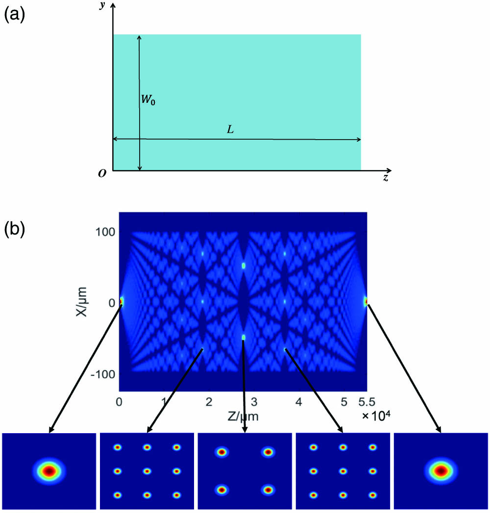
    Figure 1.(a) Schematic diagram of a square core fiber waveguide. (b) Diagram of the transmission results and the beam spots.

    It is known that the input beam can reform into one beam at the integer multiple of the imaging length [29]. The beam quality and beam profile at different integer multiples of the imaging length have been calculated, which are shown in Fig. 2. In the results, the beam spot at the length of zero is the output laser beam spot from the fiber laser, and L is the length of the square fiber when the first self-image appears. One can see that, as the multiples increase, the re-imaged beam distorts obviously, and side-lobes show up. This is due to the square core fiber not being a strongly confined waveguide, and some excited modes leak out of the core. Although there is the self-imaging effect, the effects deteriorate as more modes leak out with the increasing length of the fiber. To achieve the best self-imaging performance, the fiber length should just be the imaging length.

    Diagram of the beam quality and beam profile at different integer multiple of the imaging length.

    Figure 2.Diagram of the beam quality and beam profile at different integer multiple of the imaging length.

    Based on the above results, an all-fiber combiner has been proposed, and the schematic diagram of the all-fiber combiner based on the square fiber is shown in Fig. 3(a), which takes the 3×3 fiber array as an example. The beam combining device is composed of two parts: one is the fiber array, and the other is the square fiber. The fiber array consists of LMA passive fibers, which are loaded in a glass tube to form a square array. The fibers in the glass tube are tapered down by a given taper ratio over a prescribed taper length to form an appropriate size, which guarantees that the fiber array is injected into the square core fiber at the right position. A straight section length is often added to allow for cleaving the fused bundle. This cleaved bundle end face is then spliced to the square core fiber, which is cut into a self-imaging length. End-cap schemes, which allow the fiber mode to expand in the bulk prior to striking an air-glass interface, should be employed to increase the surface damage limit, which is not shown in Fig. 3(a). Based on the all-fiber combiner, a monolithic CBC system can be constructed, which is depicted in Fig. 3(b). The all-fiber CBC system based on the self-imaging beam combiner has three modules, including the fiber laser module, beam combining module, and phase control module. The pre-amplified narrow linewidth seed laser [generally a single-frequency laser with the linewidth around kilohertz (kHz)] is split into multiple beams, and the linewidth of the seed laser needs to be broadened to around 10–20 GHz for multi-kilowatt boosting [30]. The split beams pass through phase modulators prior to seeding the high power amplifier chain, which can actuate its phase in response to the feedback signal. If the dithering algorithms are used, the phase modulators are also used to tag the beam with a dither frequency simultaneously [31,32]. After the phase modulators, the laser beams are injected into the high power amplifier chain, which boosts the power to the several kilowatts level. The amplified laser beams are finally combined by the all-fiber combiner. A small portion of the combined output laser is picked off with a high reflector and detected with a photodetector. The photodetector output is sent to the controller, which is used as a closed-loop feedback signal to control the phase modulators. Then, the amplified beams can be combined coherently into one single beam.

    (a) Schematic diagram of the beam combining device. (b) Schematic diagram of the all-fiber CBC system with a square fiber combiner.

    Figure 3.(a) Schematic diagram of the beam combining device. (b) Schematic diagram of the all-fiber CBC system with a square fiber combiner.

    B. Numerical Design of Coherent Signal Laser Combiner

    For all-fiber CBC systems, the key component is the all-fiber combiner, which needs to be analyzed in detail. For the sake of simplicity, the 2×2 all-fiber combiner has been numerically investigated, and the calculation of the beam combining effect is based on the single-mode laser under ideal injecting conditions, which results in the relative phases between lasers being zero [26,33]. The combining length of the square fiber is calculated by the following formula [34]: L=nW2Nλ,where N is the number of the fiber array in one dimension. In the following simulations, n is 1.457, and λ is 1.064 μm. For the case considered here, the combining length is 15,720 μm.

    The influence of the NA on the beam combining effect has been calculated, and the results are shown in Fig. 4. It is assumed that the core size of the square fiber is 150 μm, and the core diameter of the fibers of the 2×2 array is 25 μm with core NA being 0.065. The variation range of core NA is from 0.2 to 0.5, which can be achieved in practical manufacturing craft by doping the core and cladding [35,36]. In Fig. 4(a), it can be seen that the beam quality of CBC has a tendency to be better as the core NA increases. This is due to the input beams exciting many modes, including guided and radiated modes, and the guided modes are more for larger core NAs, which results in more power being guided, and the beams can be reformed into one piece better. To confirm the aforementioned conclusion, the beam efficiency is calculated, which is shown in Fig. 4(b). Efficiency 1 means that the ratio of the total power of the laser is transmitted through the square fiber to the total incident power, while efficiency 2 refers to the proportion of the energy of the center main lobe. When the core NA of the square fiber is small, the loss of the power in the transmission process is larger, which results in a greater impact on beam combining. One can conclude that square fibers with a large NA should be selected as the optical waveguide material of the combiner to obtain a better combining performance.

    (a) Beam quality as a function of NA. (b) Beam efficiency as a function of NA.

    Figure 4.(a) Beam quality as a function of NA. (b) Beam efficiency as a function of NA.

    Next, the core size of the square fiber and the size of the fiber array are discussed and simulated, and the results are shown in Fig. 5. According to the results in Fig. 4, the NA is set to 0.5. To avoid the inter-fiber mode cross coupling, the minimal sizes of the cladding diameter are taken to be about three times the core diameter, corresponding to W being six times the core diameter of the input fiber, which results in the fraction of mode power at the cladding interface being negligible [16,17]. The results show that, under the same core size, the beam quality becomes worse, while the beam efficiency decreases as the square fiber core size W increases. For the fiber array composed of fiber with the core diameter being 25 μm, the M2 degrades from 1.15 to 1.7 when W increases from the minimal six times to 10.4 times of the input fiber diameter, and the efficiency reduces from 99.54% to 95.35% at the same time. One can also see that, for the same square fiber core size, the larger the fiber core size of the fiber array is, the better the beam quality and the beam efficiency will be. The M2 reduces from 1.8 to 1.2 when the input fiber core diameter at the input end of the square core fiber increases from 20 to 40 μm, while the efficiency increases from 0.96 to about 0.99 at the 240 μm square fiber core size. This is because, as the input fiber core size increases, the divergence of the beam reduces, which results in the number of the excited modes becoming less, and the leakage of laser power due to limited confined capability of the square core fiber reduces. As the W increases, the square core fiber has stronger confined capability, which also results in mitigating of laser power leakage and reforming into one beam with good beam quality. Therefore, in order to obtain the best beam quality, for a fixed core size, the smallest square fiber that can match the core size should be selected. For a fixed square fiber core size, the maximal core size that can match the square fiber core size should be selected. At the same time, it can be found that there is an optimal beam quality for each core diameter of the fiber array. The optimal case is the case where the core size of the square fiber is the smallest under the condition of the core diameter.

    (a) Beam quality as a function of fiber core size and square fiber core size. (b) Beam efficiency as a function of fiber core size and square fiber core size.

    Figure 5.(a) Beam quality as a function of fiber core size and square fiber core size. (b) Beam efficiency as a function of fiber core size and square fiber core size.

    It is shown in Fig. 5(a) that the optimal beam quality achieved for each case is different, which needs to be analyzed further. The optimal beam quality that can be achieved for different input fiber core diameters has been calculated, which is shown in Fig. 6. The NA is set to 0.5. The core diameter of the input fiber of the fiber array is set from 20 to 50 μm. In order to compare the best combining effect at different core diameters of the fiber array, for each core diameter of the input fiber, according to the results in Fig. 5, the smallest size of the square fiber that can achieve combination is selected, which is equal to six times the core diameter of the input fiber. So, the core size of the square fiber is in a range of 120–300 μm, as the core diameter of the input fiber of the fiber array changes. One can see that, as the input fiber core diameter increases, the achievable maximal combining performance becomes better. However, the combining performance degrades as the input fiber core diameter increases beyond 30 μm, and the M2 increases to 1.3, while the efficiency reduces to 0.97. This is the conjunction effects of input fiber core diameter and square core fiber diameter. One should also note that the degradation of the achievable maximal combining performance is moderate.

    (a) Optimal beam quality as a function of fiber core size. (b) Beam efficiency as a function of fiber core size with W being six times the input fiber core size.

    Figure 6.(a) Optimal beam quality as a function of fiber core size. (b) Beam efficiency as a function of fiber core size with W being six times the input fiber core size.

    In the above simulations, the 2×2 combiners have been taken as an example, and the combination channel is limited to four. It is important to analyze the scaling capability of the combination channel, which limited the power scaling capability of the proposed all-fiber CBC. The fiber arrays of 3×3, 4×4, and 5×5 were simulated to study the influence of the number of input fibers on the all-fiber CBC beam combination, which have been shown in Fig. 7. In order to simplify the calculation, the NA is set to 0.5, and the core size of the fibers of the fiber array is set to 25 μm with the cladding size being 75 μm. So, the core size of the square fiber is 150 μm when the fiber array is 2×2 and 375 μm when the fiber array is 5×5, which changes as the number of the fiber array changes. One can see that, as the number of the fiber array increases, the beam quality becomes worse, and the efficiency decreases, which means that the channel scaling capability is limited. As the core NA increases, the degradation can be reduced, which means that the limitation can be raised by increasing the core NA of the square fiber. One of the possible solutions is to employ a square core fiber with air acting directly as the cladding. Then, the M2 and efficiency of the 5×5 case are 1.95 and 98.9%, respectively. It is difficult to manufacture the bare square fiber, and, for high power operation, the hold or package of the bare square fiber is a big challenge. Another possible solution is to employ the output fiber of fiber array with ultra-low core NA, such as the core NA being 0.03, which can expand the mode field due to the weaker mode field confining capability. When the fibers with the core NA being 0.03 have been employed, the M2 and efficiency of the 5×5 case are 1.97 and 98.7%, respectively. The intensity distribution of the 5×5 fiber array has been shown in Fig. 7(c) with the NA being 0.2, and the intensity profile along the x direction has been plotted with that of the 2×2 fiber array for comparison in Fig. 7(d). One can see that there are side-lobes around the main lobe for the 5×5 case, but the power contained in the side-lobes is less than 3%. Due to the M2 being calculated by fitting the beam width, which was calculated by using the rigorous second moment definition [37], the value of M2 is highly sensitive to the presence of side-lobes, and even a small fraction of power in the side-lobes results in significant degradation of M2. If the side-lobes are truncated, the M2 becomes 1.2, which means that >97% power maintains diffraction-limited beam quality. However, the M2 of un-truncated beam is sensitive to the parameter variation and can reflect the influence of various parameters, which is used as the evaluation index in the paper.

    (a) Beam quality as a function of NA with different fiber arrays. (b) Beam efficiency as a function of NA with different fiber arrays. (c) Diagram of typical intensity distribution of a 5×5 fiber array after combination. (d) Diagram of the intensity profiles of the combining beam spot of a 2×2 fiber array and a 5×5 fiber array along the x direction.

    Figure 7.(a) Beam quality as a function of NA with different fiber arrays. (b) Beam efficiency as a function of NA with different fiber arrays. (c) Diagram of typical intensity distribution of a 5×5 fiber array after combination. (d) Diagram of the intensity profiles of the combining beam spot of a 2×2 fiber array and a 5×5 fiber array along the x direction.

    Based on the above results, one can conclude that, to achieve the best combining performance under the present conditions, the combiner should be composed of a 2×2 fiber array with a 25 μm fiber core and a 150 μm core size square fiber with the largest achievable core NA possible. Under the above conditions, when the four laser beams are input into the beam combiner, the combined beam is simulated. The other parameters are the same as those in the calculations above. The simulation results have been shown in Fig. 8. The intensity distributions of the input fiber array are shown in Fig. 8(a), and the intensity distribution of the combined beam is shown in Fig. 8(b), where no side-lobes are being observed. The beam quality is calculated to be 1.147, and the combining efficiency is 99.54%, which means that the discrete array can be reformed into one beam perfectly through optimizing the parameters.

    (a) Input intensity distribution with the 2×2 fiber array. (b) Output intensity distribution after combination with the 2×2 fiber array.

    Figure 8.(a) Input intensity distribution with the 2×2 fiber array. (b) Output intensity distribution after combination with the 2×2 fiber array.

    C. Discussion

    In Section 2.B, the fibers are arranged into an array and then fused with the square fiber, which results in the coherent combination efficiency being above 97%. For comparison, the coherent combination of the fiber array without a square fiber, similar to the lens arrays, has been simulated, as shown in Fig. 9, and the results of those with the square fiber have also been listed. The 2×2 array and 3×3 array have been simulated, and the size of the output fiber of the fiber array is 25 μm/75 μm. The NA of the output fiber is 0.06. The core size of the square fiber in the case of the 2×2 fiber array is 150 μm, while it is 225 μm in the case of the 3×3 fiber array. The NA of the square fiber is 0.5. One can see that there are many periodic side-lobes instead of one single spot. The combination efficiency has been calculated, which is about only 2.8% and 0.7% for the 2×2 array and 3×3 array, respectively, and it is significantly lower than those achieved by the fiber array with a square fiber (99.54% for the 2×2 array and 99.07% for the 3×3 array). This is because the fiber array without the square fiber is equivalent to tilled aperture coherent combining schemes with low fill factor of 0.29 [38]. It is well known that fiber arrays with lower fill factors result in more side-lobes and smaller combination efficiency. Higher combination efficiency can be achieved by an excellent robust design, but the demonstrated combination efficiency is 50% with the fill factor being 0.93 [39]. Due to the Gaussian shape of the laser spot, even the theoretical maximal energy contained in the main lobe is smaller than 82% [40]. One can conclude that, compared with the tilled aperture coherent combination, the employing of the self-imaging effect in the square fiber can overcome the influence of limited fill factor, and greatly improve the beam combination performance.

    (a) Diagram of output intensity distribution from the 2×2 fiber array. (b) Diagram of output intensity distribution after combination with the tilled aperture in the case of the 2×2 fiber array. (c) Diagram of output intensity distribution after combination with the square fiber in the case of the 2×2 fiber array. (d) Diagram of output intensity distribution from the 3×3 fiber array. (e) Diagram of output intensity distribution after combination with the tilled aperture in the case of the 3×3 fiber array. (f) Diagram of output intensity distribution after combination with the square fiber in the case of the 3×3 fiber array.

    Figure 9.(a) Diagram of output intensity distribution from the 2×2 fiber array. (b) Diagram of output intensity distribution after combination with the tilled aperture in the case of the 2×2 fiber array. (c) Diagram of output intensity distribution after combination with the square fiber in the case of the 2×2 fiber array. (d) Diagram of output intensity distribution from the 3×3 fiber array. (e) Diagram of output intensity distribution after combination with the tilled aperture in the case of the 3×3 fiber array. (f) Diagram of output intensity distribution after combination with the square fiber in the case of the 3×3 fiber array.

    It is known that the broadening of the laser linewidth can result in reduction of combining efficiency [41]. This can be eliminated through employing optical delay lines, and fiber sources with several tens of nanometers linewidth have been coherently combined with high efficiency [2,42]. On the other hand, the self-imaging length is dependent on center wavelength, as shown in Eq. (3), which means that the broadband linewidth may cause efficiency loss due to the mismatch of self-imaging length for different wavelength components. To analyze the effect quantitatively, the combining of two different wavelengths has been calculated with the self-imaging length chosen to correspond to only one wavelength. The calculation is still based on the 2×2 fiber array. The size of the output fiber of the fiber array is 25 μm/75 μm, and the core size of the square fiber is 150 μm. The NA of the square fiber is set to 0.5. The length of the square fiber is 15,680 μm, which is a combining length of the 1.060 μm laser using the self-image effect to combine. The wavelength of the laser changes from 1.060 to 1.080 μm. The results are shown in Fig. 10. From the results, it can be seen that when the wavelength changes from 1.060 to 1.080 μm, the beam quality changes from 1.18 to 1.30, and the beam combining efficiency decreases slightly from 99.5% to 97.4%. Generally, the linewidth of fiber sources used in coherent combination is on the order of 10 GHz [2,9,10,43], which means that the mismatch caused by finite linewidth has little impact on the combining performance.

    (a) Beam quality as a function of wavelength. (b) Beam efficiency as a function of wavelength.

    Figure 10.(a) Beam quality as a function of wavelength. (b) Beam efficiency as a function of wavelength.

    Then, the influence of the vibration and thermal effect on beam combination of the square fiber is analyzed. As described in Section 2.A, the scheme of coherent beam combining using the self-imaging effect of the square fiber is a coherent combining scheme of all optical fibers, and the advantages of the all-fiber system lie in its compact structure and great anti-disturbance ability. For the thermal effect on the combination, the influence on the square fiber is mainly discussed. According to the thermal expansion formula, the change in the size of the square fiber when the temperature is increased by 100°C is calculated. The formula can be expressed as follows [44]: ΔL=α×L×ΔT,where ΔL is the deformation length, α is the thermal expansion coefficient, and the α of quartz is 5.5×10⁷°C1. L is the original length, and ΔT is the change of the temperature. If the temperature rises by 100°C without any cooling methods, the core size of the square fiber is 150 μm, and the length is assumed as 15,720 μm. After calculation, the change of the core size is 0.0083 μm, and the change of the length is 0.8646 μm. Simulation of the beam combining effect on the deformed square optical fiber is performed, and it has negligible effect on the combining effect. It shows that the change of the length caused by the thermal effect is so small that it has little effect on the combining effect. Besides, there are also very mature cooling methods, such as water cooling after packaging, to dissipate the waste heat in optical fiber components, and IPG Photonics has delivered a 500 kW commercial multimode fiber laser [45]. It shows that the heat dissipation problem under high power can be solved very well. At present, there is already a square fiber with an 800 μm core diameter, as shown in Ref. [46]. According to the calculation, the all-fiber combiner with an about 10×10 array of 75 μm fiber can be fabricated with the matured fiber component manufacture craft. The beam combining efficiency for different fiber arrays has been fitted for NA=0.2 and NA=0.5, which is shown in Fig. 11. Polynomial curve fitting has been employed to achieve the efficiency equations for NA=0.2 and NA=0.5. Based on the fitted equations, one can find that the beam combining efficiency of the 10×10 fiber array is about 89.27% for the square fiber with NA being 0.2, while it is about 93.47% for the square fiber with NA being 0.5. It reveals that, even under the 10×10 fiber array, high combination efficiency can be achieved by properly designing the square core fiber parameters. Meanwhile, active phase control of more than 100 channels has already been demonstrated [11], and the beam combinable fiber lasers have been scaled up to above 3 kW [47,48]. Due to the 500 kW multimode signal combiner being reported by IPG Photonics [45], one can conclude that the power handling capability of the all-fiber combiner can be handled well through clever thermal management, and the proposed all-fiber combiner based on the square fiber has a good scalability to >300  kW.

    Diagram of the comparison and data fitting of the combining efficiency of different fiber arrays.

    Figure 11.Diagram of the comparison and data fitting of the combining efficiency of different fiber arrays.

    3. DEMONSTRATION OF COHERENT BEAM DE-COMBINATION IN SQUARE CORE FIBER

    A. Experimental Setup

    Experimental study has been carried out to verify the self-imaging effect in the square fiber. According to the results of the simulation above, LMA fibers with the core/cladding diameters being 25 μm/400 μm were chosen to deliver the laser. To match the output fiber and follow the principle of choosing the least square fiber core size, a square fiber with 200 μm core size and 440 μm cladding size was used. The core NA of the square fiber is 0.22. The cross section of the square fiber observed under the microscope is shown in Fig. 12. One can see that the shape of the cladding of the square fiber is a circle, which makes the connection between the laser delivering fiber and the square fiber more convenient. Under the microscope, the actual size of the cross section of the square fiber is measured, and the side length of the square fiber is measured as 200 μm. It can be seen from Fig. 12 that the four corners of the square fiber are not right angles but rounded corners. The radius of the rounded corners is measured to be 18 μm. The angles between the adjacent sides of the square fiber are also measured and marked in Fig. 12.

    Diagram of the cross section of the square fiber.

    Figure 12.Diagram of the cross section of the square fiber.

    The experimental setup is shown in Fig. 13. The laser source is a linearly polarized single-frequency distributed feedback (DFB) laser, which was boosted by a piece of LMA polarization-maintaining ytterbium-doped fiber with the core/cladding diameter being 10 μm/125 μm. An isolator (ISO) has been employed to protect the seed from the influence of backward light. The amplifier was co-pumped, and the pump power was injected into the amplifier through a (2+1)×1 signal/pump combiner. The residual pump power and cladding signal light were stripped by a home-made cladding power stripper (CPS) [49]. The signal laser was boosted to 400 mW, and it passed through another ISO to the 25/400 LMA fiber, which is generally employed in multi-kilowatt-level fiber laser systems [24,50]. A mode field adaptor (MFA) was employed to accommodate the output fiber of the ISO with the 25/400 LMA fiber and to maintain the single-mode beam quality. All of the fibers and the components of the laser system were polarization-maintaining ones to ensure linear polarization of the output laser. The output fiber of the MFA has been spliced to the square fiber, which has a core size of 200 μm. The output laser from the square fiber was collimated by a collimating lens and then focused by a convex lens, which was finally detected and observed on the charge-coupled device (CCD).

    Diagram of the experimental structure.

    Figure 13.Diagram of the experimental structure.

    B. Results and Analysis

    The laser beam from MFA was measured first, which is shown in Fig. 14. With the MFA to match the mode field, near single-mode beam quality has been achieved, and, according to the instruction of the M2 meter, the spot size around the waist position is measured to figure out the size of the waist and far field divergence angle, which has been used to calculate the M2. In the experiment, the M2-200S-FW was used to detect the spot and calculate the M2, which was measured to be 1.288/1.312.

    (a) Diagram of the beam spot from MFA. (b) M2 measurement of the laser beam from MFA with the 4σ method.

    Figure 14.(a) Diagram of the beam spot from MFA. (b) M2 measurement of the laser beam from MFA with the 4σ method.

    The fiber had an index of approximately 1.457 and an aperture of approximately 200 μm, which results in the self-imaging length of the square fiber being calculated to be 5.5 cm from Eq. (3). The output fiber of the MFA has been spliced to the square fiber carefully to avoid lateral offset error, and the side view of the splice point between the output fiber and the square core fiber is shown in Fig. 15.

    Diagram of the side view of the splice point between the output fiber and the square core fiber.

    Figure 15.Diagram of the side view of the splice point between the output fiber and the square core fiber.

    The beam spots at 5.5 cm and 11 cm were measured and are shown in Fig. 16. One can see that the Gaussian beam has been achieved at the self-imaging length, which degrades dramatically as the length is taken to be two times that of the self-imaging length. The M2 at 5.5 cm is measured to be 2.038/1.900 by using the second moment definition of beam size, and the corresponding efficiency is about 65%, which is far lower than the theoretical efficiency predicted in Section 2. This is due to the dimensional errors in the square core fiber, and the power has been redistributed in the side-lobes around the main spot. One can see from Fig. 12 that the square core fiber has a large round corner, which undermines the self-imaging quality. To evaluate the impact qualitatively, the self-imaging efficiency of the square fiber has been simulated, and the parameters were set to be the same as those in the experiment. The calculated efficiency is about 70%, which means that the round corner is the main errors. Additional efficiency reduction of 5% was caused by the non-square core, splicing error, length error, and so on.

    (a) Diagram of the beam spot at the 5.5 cm length of the square fiber. (b) Diagram of the beam spot at the 11 cm length of the square fiber. (c) M2 measurement of the laser beam at the length of 5.5 cm of the square fiber with the 4σ method.

    Figure 16.(a) Diagram of the beam spot at the 5.5 cm length of the square fiber. (b) Diagram of the beam spot at the 11 cm length of the square fiber. (c) M2 measurement of the laser beam at the length of 5.5 cm of the square fiber with the 4σ method.

    Regardless of the specific optical realization, one component can act as splitter, and it can be used as combiner in reverse, which means that the split properties of the square fiber can be a good guide for its performance in combination. Then, the square fiber was used as a beam splitter, and the square core fiber was cut into a half length of 2.75 cm, which was then shortened to 1.83 cm to create the 3×3 image. The measured beam intensity distributions have been shown in Fig. 17, and the numerical results have also been listed for comparison. At the position of the 2×2 images, it can be seen that the energy of each spot goes down, and the energy is distributed near-evenly among the four spots, which is about 15.5% of the total energy. At the position of the 3×3 images, the phenomena are similar: the energy is distributed near-evenly among the four spots, which is about 8.4% of the total energy. One can also note that, apart from the main beam spots, there were side-lobes, which is due to the dimensional errors of the square core fiber as discussed above. The total power of the 3×3 that is higher than that of the 2×2 is due to the length of the square fiber being shortened, which results in the influence of the dimensional errors weakening. One can see that the experimental results agree well with the numerical simulation results, which means that according to the principle of optical path reversibility a fiber array is input through a square fiber of a specific length, and finally one laser spot can be output to achieve coherent combination. So, it proves that the square core fiber can act as a coherent beam splitter as well as a combiner.

    Theoretical and experimental comparison of the self-imaging effect in the square fiber.

    Figure 17.Theoretical and experimental comparison of the self-imaging effect in the square fiber.

    4. CONCLUSION

    In this paper, the self-imaging effect of the square fiber has been investigated, and an all-fiber combiner for coherent combining applications has been proposed. The influence of various parameters has been studied numerically. From the results, it can be seen that the NA and the core size of the square fiber, the size, and the number of the fiber array all affect the beam combining effect. The degradation of beam quality in the combined beam is mainly due to the generation of side-lobes. If the side-lobes are truncated, the beam quality is close to the diffraction limit. By simulating different parameters of the beam combiner, good performance parameters and optimized directions of the beam combiner can be obtained.

    An experiment is carried out to verify the self-imaging of the square fiber. The experimental results show that the square fiber can act as a self-imaging waveguide, but the performance degrades as the imaging length increases. The energy loss and the appearance of side spots are also analyzed by detecting the beam spots in different positions. The experimental results agree well with the theoretical results, which further prove the feasibility of the square fiber for CBC. In the future, experiments on an all-fiber combiner will be carried out.

    References

    [1] D. J. Richardson, J. Nilsson, W. A. Clarkson. High power fiber lasers: current status and future perspectives. J. Opt. Soc. Am. B, 27, B63-B92(2010).

    [2] Z. Liu, X. Jin, R. Su, P. Ma, P. Zhou. Development status of high power fiber lasers and their coherent beam combination. Sci. China Inf. Sci., 62, 1-32(2019).

    [3] W. Shi, A. Schulzgen, R. Amezcua, X. Zhu, S.-U. Alam. Fiber lasers and their applications: introduction. J. Opt. Soc. Am. B, 34, FLA1(2017).

    [4] J. Zhu, P. Zhou, Y. Ma, X. Xu, Z. Liu. Power scaling analysis of tandem-pumped Yb-doped fiber lasers and amplifiers. Opt. Express, 19, 18645-18654(2011).

    [5] R. Tao, X. Wang, P. Zhou. Comprehensive theoretical study of mode instability in high-power fiber lasers by employing a universal model and its implications. IEEE J. Sel. Top. Quantum Electron., 24, 0903319(2018).

    [6] M. N. Zervas. Transverse mode instability, thermal lensing and power scaling in Yb3+-doped high-power fiber amplifiers. Opt. Express, 27, 19019-19041(2019).

    [7] Z. Liu, P. Ma, R. Su, R. Tao, Y. Ma, X. Wang, P. Zhou. High-power coherent beam polarization combination of fiber lasers: progress and prospect [Invited]. J. Opt. Soc. Am. B, 34, A7-A14(2017).

    [8] T. Y. Fan. Laser beam combining for high-power, high-radiance sources. IEEE J. Sel. Top. Quantum Electron., 11, 567-577(2005).

    [9] A. Flores, I. Dajani, R. Holten, T. Ehrenreich, B. Andersona. Multi-kilowatt diffractive coherent combining of pseudorandom-modulated fiber amplifiers. Opt. Eng., 55, 096101(2016).

    [10] P. Ma, H. Chang, Y. Ma, R. Su, J. Zhou. 7.1 kW coherent beam combining system based on a seven-channel fiber amplifier array. Opt. Laser Technol., 140, 107016(2021).

    [11] H. Chang, Q. Chang, J. Xi, T. Hou, R. Su, P. Ma, J. Wu, C. Li, M. Jiang, Y. Ma, P. Zhou. First experimental demonstration of coherent beam combining of more than 100 beams. Photon. Res., 8, 1943-1948(2020).

    [12] S. Chen, Y. Li, K. Lu. Branch arm filtered coherent combining of tunable fiber lasers. Opt. Express, 13, 7878-7883(2005).

    [13] M. Karow, J. Neumann, D. Kracht, P. Wessels. Impact of amplified spontaneous emission on Brillouin scattering of a single-frequency signal. Opt. Express, 20, 10572-10582(2012).

    [14] E. A. Shcherbakov, V. V. Fomin, A. A. Abramov, A. A. Ferin, D. V. Mochalov, V. P. Gapontsev. Industrial grade 100 kW power CW fiber laser. Advanced Solid-State Lasers Congress, ATh4A.2(2013).

    [15] P. Zhou, L. Huang, J. Leng, H. Xiao, J. Xu, T. Yao. High-power double-clad fiber lasers: 30 years of development. Sci. Chin. Technol., 50, 123-135(2020).

    [16] J. E. Rothenberg. All-fiber integrated high power coherent beam combination. U.S. patent(2012).

    [17] J. E. Rothenberg, E. C. T. Cheung. Integrated spectral and all-fiber coherent beam combination. U.S. patent(2012).

    [18] J. Li, H. Zhao, Z. Chen, X. Wang, X. Xu. All-fiber active coherent combining via a fiber combiner. Opt. Commun., 286, 273-276(2013).

    [19] B. Yang, X. Wang, P. Ma, Z. Pu, X. Xu. Active phase locking of four Yb-doped fiber amplifiers with a multi-mode fiber combiner. International Photonics and OptoElectronics Meetings, JF2A.6(2014).

    [20] R. Uberna, A. Bratcher, T. G. Alley, A. D. Sanchez, A. S. Flores, B. Pulford. Coherent combination of high power fiber amplifiers in a two-dimensional re-imaging waveguide. Opt. Express, 18, 13547-13553(2010).

    [21] J. W. Dawson, M. J. Messerly, R. J. Beach, M. Y. Shverdin, E. A. Stappaerts, A. K. Sridharan, P. H. Pax, J. E. Heebner, C. W. Siders, C. P. J. Barty. Analysis of the scalability of diffraction-limited fiber lasers and amplifiers to high average power. Opt. Express, 16, 13240-13266(2008).

    [22] R. Tao, L. Si, Y. Ma, P. Zhou, Z. Liu. Coherent beam combination of fiber lasers with a strongly confined waveguide: numerical model. Appl. Opt., 51, 5826-5833(2012).

    [23] C. K. Jen, J. E. B. Oliveira, N. Goto, K. Abe. Role of guided acoustic-wave properties in single-mode optical fiber design. Electron. Lett., 24, 1419-1420(1988).

    [24] H. Lin, R. Tao, C. Li, B. Wang, C. Guo, Q. Shu, P. Zhao, L. Xu, J. Wang, F. Jing, Q. Chu. 3.7 kW monolithic narrow linewidth single mode fiber laser through simultaneously suppressing nonlinear effects and mode instability. Opt. Express, 27, 9716-9724(2019).

    [25] R. Tao, R. Su, P. Ma, X. Wang, P. Zhou. Suppressing mode instabilities by optimizing the fiber coiling methods. Laser Phys. Lett., 14, 025101(2017).

    [26] R. Tao, X. Wang, P. Zhou, L. Si. Analysis of the effects of mismatched errors on coherent beam combining based on a self-imaging waveguide. Quantum Electron., 46, 61-67(2016).

    [27] R. Scarmozzino, A. Gopinath, R. Pregla, S. Helfert. Numerical techniques for modeling guided-wave photonic devices. IEEE J. Sel. Top. Quantum Electron., 6, 150-162(2000).

    [28] R. Scarmozzino, R. M. Osgood. Comparison of finite-difference and Fourier-transform solutions of the parabolic wave equation with emphasis on integrated-optics applications. J. Opt. Soc. Am. A, 8, 724-731(1991).

    [29] O. Bryngdahl. Image formation using self-imaging techniques. J. Opt. Soc. Am. B, 63, 416-419(1973).

    [30] I. Dajani, A. Flores, R. Holten, B. Anderson, B. Pulford, T. Ehrenreich. Multi-kilowatt power scaling and coherent beam combining of narrow-linewidth fiber lasers. Proc. SPIE, 9728, 972801(2016).

    [31] Y. Ma, P. Zhou, X. Wang, H. Ma, X. Xu, L. Si, Z. Liu, Y. Zhao. Coherent beam combination with single frequency dithering technique. Opt. Lett., 35, 1308-1310(2010).

    [32] R. Tao, Y. Ma, L. Si, X. Dong, P. Zhou, Z. Liu. Target-in-the-loop high-power adaptive phase-locked fiber laser array using single-frequency dithering technique. Appl. Phys. B, 105, 285-291(2011).

    [33] M. Bachmann, P. A. Besse, H. Melchior. General self-imaging properties in N × N multimode interference couplers including phase relations. Appl. Opt., 33, 3905-3911(1994).

    [34] R. Tao, X. Wang, H. Xiao, P. Zhou, L. Si. Coherent beam combination of fiber lasers with a strongly confined tapered self-imaging waveguide: theoretical modeling and simulation. Photon. Res., 1, 186-196(2013).

    [35] M. C. Paul, R. Sen, T. Bandyopadhyay. Fluorine incorporation in silica glass by MCVD process—a critical study. J. Mater. Sci., 32, 3511-3516(1997).

    [36] S. R. Nagel, J. B. Macchesney, K. L. Walker. An overview of the modified chemical vapor-deposition (MCVD) process and performance. IEEE J. Quantum Electron., 18, 459-476(1982).

    [37] A. E. Siegman. How to (maybe) measure laser beam quality. DPSS (Diode Pumped Solid State) Lasers: Applications and Issues, MQ1(1998).

    [38] R. Tao, L. Si, Y. Ma, P. Zhou, Z. Liu. Propagation of coherently combined truncated laser beam arrays with beam distortions in non-Kolmogorov turbulence. Appl. Opt., 51, 5609-5618(2012).

    [39] I. Fsaifes, L. Daniault, S. Bellanger, M. Veinhard, J. Bourderionnet, C. Larat, E. Lallier, E. Durand, A. Brignon, J. C. Chanteloup. Coherent beam combining of 61 femtosecond fiber amplifiers. Opt. Express, 28, 20152-20161(2020).

    [40] P. Zhou, X. Wang, Y. Ma, H. Ma, Z. Liu, X. Xu. Optimal truncation of element beam in a coherent fiber laser array. Chin. Phys. Lett., 26, 044206(2009).

    [41] G. D. Goodno, C. C. Shih, J. E. Rothenberg. Perturbative analysis of coherent combining efficiency with mismatched lasers. Opt. Express, 18, 25403-25414(2010).

    [42] M. Muller, C. Aleshire, A. Klenke, E. Haddad, F. Legare, A. Tunnermann, J. Limpert. 10.4 kW coherently combined ultrafast fiber laser. Opt. Lett., 45, 3083-3086(2020).

    [43] X. Wang, P. Zhou, R. Su, P. Ma, R. Tao, Y. Ma, X. Xu, Z. Liu. Current situation, tendency and challenge of coherent combining of high power fiber lasers. Chin. J. Lasers, 44, 0201001(2017).

    [44] Y. S. Touloukian, R. K. Kirby, R. E. Taylor, P. D. Desai. Thermal Expansion: Metallic Elements and Alloys. Thermophysical Properties of Matter, 12(1975).

    [45] https://www.ipgphotonics.com. https://www.ipgphotonics.com

    [46] https://www.ceramoptec.com/industrial-products/fibers/optran-uv-ncc-/-wf-ncc.html. https://www.ceramoptec.com/industrial-products/fibers/optran-uv-ncc-/-wf-ncc.html

    [47] Y. Wang, Y. Sun, W. Peng, Y. Feng, J. Wang, Y. Ma, Q. Gao, R. Zhu, C. Tang. 3.25 kW all-fiberized and polarization-maintained Yb-doped amplifier with a 20 GHz linewidth and near-diffraction-limited beam quality. Appl. Opt., 60, 6331-6336(2021).

    [48] Z. Huang, Q. Shu, R. Tao, Q. Chu, Y. Luo, D. Yan, X. Feng, Y. Liu, W. Wu, H. Zhang, H. Lin, J. Wang, F. Jing. > 5 kW record high power narrow linewidth laser from traditional step-index monolithic fiber amplifier. IEEE Photon. Technol. Lett., 33, 1181-1184(2021).

    [49] Y. Liu, S. Huang, W. Wu, P. Zhao, X. Tang, X. Feng, M. Li, B. Shen, H. Song, R. Tao, J. Wang. 2 kW high stability robust fiber cladding mode stripper with moderate package temperature rising. IEEE Photon. Technol. Lett., 32, 1151-1154(2020).

    [50] B. Yang, W. Peng, H. Zhang, X. Xi, X. Xu. 6 kW single mode monolithic fiber laser enabled by effective mitigation of the transverse mode instability. Opt. Express, 29, 26366-26374(2021).

    Yuefang Yan, Yu Liu, Haoyu Zhang, Yue Li, Yuwei Li, Xi Feng, Donglin Yan, Jianjun Wang, Honghuan Lin, Feng Jing, Wenhui Huang, Rumao Tao. Principle and numerical demonstration of high power all-fiber coherent beam combination based on self-imaging effect in a square core fiber[J]. Photonics Research, 2022, 10(2): 444
    Download Citation