
Guozhu Hou, Lijun Lv, Yiqing Cao. Fish-eye lens system design based on sixth-order wave aberration theory[J]. Infrared and Laser Engineering, 2021, 50(6): 20200505
- Infrared and Laser Engineering
- Vol. 50, Issue 6, 20200505 (2021)
Abstract
Keywords
0 Introduction
In recent years, large field of view (FOV) angle optical imaging system, such as fish-eye lens and catadioptric panoramic imaging system, have attracted more and more attention. It has been widely used in robot or vehicle navigation, positioning, scene monitoring, external space detection, micro intelligent system and so on. In daily life, the fish-eye lenses are also used by many photography enthusiasts. In April 2015, Ricoh released a 360° panoramic camera, which used two fish-eye lens systems with a field of view angle more than 180° to realize the imaging of the three-dimensional angle of the whole space, causing people’s attention all over the world.
The field of view angle of fish-eye lens system reach or even exceed 180°. The beam focus, wave array surface and aberration of the optical system in the meridian and sagittal plane are totally different, which has the imaging characteristics of the plane symmetric optical system. At the same time, people often pursue the large aperture imaging (e.g. F#<3). Therefore, this kind of system has three characteristics: plane symmetry, super large field of view, and large aperture imaging, which make the design of fish-eye lens optical system very complex. Aberration theory is an important means to study optical system. Because of the plane symmetry imaging characteristics for this kind of lens system. Seidel primary aberration and high-order aberration theories that develop from axisymmetric optical system are no longer suitable for aberration analysis and design of this super large field of view optical system.
The conventional lens design of different structures and their aberration characteristics are quite clear[
For the optical system of large aperture imaging, the effect of higher-order aberrations becomes significant[
It is a classical method to solve optical system aberration with wave aberration theory, and it is more suitable for the aberration analysis and calculation of multi-element optical system. For a multi-element optical system, the total system wave aberration is the sum of the wave aberrations for each elements. However, the derivation model of the wave aberration expression with a single element generally assume that the object point is an ideal geometric object point. According to the first-order optical surface parameters, the correlation ray path is expanded into a series of pupil coordinates and field angle, and then every order wave aberration expression (called intrinsic wave aberrations) is obtained. Except for the first optical plane, the other optical plane in a multi-element optical system, due to the aberration influence by its front optical system, the assumption of the ideal geometry point is not tenable in a strict sense. Therefore, the intrinsic wave aberration only reflect the single system element aberration in a real sense. The intrinsic wave aberration ahead of system will produce a correction amount of wave aberration (called derivative wave aberration), which is related to the intrinsic wave aberration of the optical plane and the optical system ahead of it. Therefore, the aberration with multi-element optical system is composed of the intrinsic aberration and the derivative aberration. For large aperture imaging optical system, the contribution of derivative aberration cannot be ignored. The evolution process of higher-order intrinsic aberration is basically the same as that of lower-order intrinsic aberration, but the evolution ideas of derivative aberrations and intrinsic aberrations are totally different. The research on derivative aberrations for the plane symmetric optical system cannot directly apply the derivative aberrations methods by axisymmetric optical system. Secondly, for the paraxial optical system aberration, the light pupil coordinates transmission on the adjacent optical surface is generally treated as in a linear way, the nonlinear term contribution is generally small and its influence on the aberration can be ignored. However, for a large field of view optical system, such as a fish-eye lens, the light beams from object with large field of view hit the optical surface. If the pupil coordinates transmission between adjacent optical surfaces is still treated as a linear way, there will be more calculation error with the increase of aperture. Through the research on many fish-eye lens systems, it is shown that the nonlinear term in the pupil coordinate transfer relationship has a significant effect on the object point wave aberration in a large field of view optical system, even more than the derivative wave aberration.
The basic structure of the fish-eye lens is composed of the former group with several large negative meniscus optical power lenses and the latter group with several common objective lenses. The former group is mainly used to compress the field angle. Most of the aberration analysis involved in the fish-eye lens research reports is still based on Seidel’s primary aberration theory. Dai Jianning, in his doctoral dissertation on fish-eye lens research[
In some professional optical design software, the sampling optical light path difference is mostly used to simulate the wave aberration distribution at the exit pupil of optical system, and then calculate the optical system transfer function to evaluate its imaging and its accuracy, that all depend on the number of sampling light. The evaluation function based on the wave aberration theory includes only one or several aberrations contribution. In addition, it is different from the calculation method of light sampling.
1 Sixth-order wave aberration theory
The sixth-order wave aberration theory mainly include the sixth-order intrinsic wave aberration, the fifth order aberration, and the derivative wave aberration and the influence of the second order precision of pupil coordinates on the wave aberration of plane symmetric optical system.
1.1 The sixth-order intrinsic wave aberrations
According to the fourth-order wave aberration theory of plane symmetric optical system developed by Lu Lijun, the sixth-order accuracy expressions of meridian and sagittal focal line with respect to pupil coordinates are obtained by using the torus as the reference wave surface[
The wave aberration calculation is based on the first-order optical system parameters. The parameters of the main light ray in the optical path are calculated using the main light ray transfer equation. Based on the first-order and the second-order wave aberration coefficients (monochromatic aberration is calculated for D light), the object and the image distance of each optical plane in the meridian and sagittal plane are determined. These basic optical path parameters can be used to calculate the each order wave aberration coefficients of the optical system[
1.2 The fifth-order aberration
The solution of the fifth-order aberration is the same as the original fourth-order wave aberration theory, but the correlation expression is required to keep the sixth-order accuracy. The first-order to the third-order aberration coefficients are consistent with the original fourth-order wave aberration theory. The fourth-order and fifth-order meridional and sagittal aberration coefficients are d400, d220, d040, d500, d320, d140, h310, h130, h410, h230, h050 respectively.
1.3 Transverse aberrations and the influence of the second-order accuracy of the aperture ray on the wave aberration
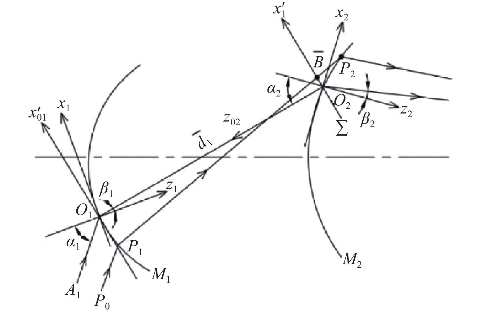
As shown in Fig.1, it shows the relevant coordinate systems used in the main ray transmission and aberration calculation. In the process of calculation, all the relevant coordinate systems adopt the right hand rule, and the positive direction of y-axis is from the inside to the outside, x1O1z1 and x2O2z2 are the optical surface coordinate systems of M1 and M2 respectively. P0P1P2 is any aperture ray, and A1O1O2 is the main ray.
![]()
Figure 1.Optical scheme of an aperture ray
1.3.1 Influence of transverse wave aberration on pupil coordinates
Figure 2 shows two element systems consisting of M1 and M2 optical surfaces. P1P2B is any aperture ray, A1O1O2 is the main ray, x′01O1y′01 is the outgoing wave array coordinate system of M1, x02O2y02 and x′02O2y′02 are the incoming and outgoing wave array coordinate systems of M2, and
![]()
Figure 2.Coordinate systems of the wave surface and the image plane in the reverse optical path of a double-element optical system
The coordinate (x2, y2) of the light on M2 are the pupil reference optical coordinate system. The reverse optical path is used to calculate the wave aberration of optical surface M2 on M1, and to correct the pupil coordinates of M1. In Fig.2,
Therefore
In the above formula,
Since the aberration Δx01′ and Δy01′ are generally very small, they are transformed into the surface coordinate system of M1 by linear approximation.
1.3.2 Influence of the second-order transmission accuracy of pupil coordinates on wave aberration
The total wave aberration of multi-element optical system is the linear sum of each element wave aberration. When calculating the wave aberration with aberration theory, it is necessary to convert the light pupil coordinates on each element into the pupil reference coordinates of the final optical element. As shown in Fig.1, by using the spatial ray equation and polynomial fitting method (excluding the influence of wave aberration), the second-order accuracy relation between the coordinates P1(x1,y1) and P2(x2,y2) at the intersection of ray and optical surface M1 and M2 is obtained. As follows:
In the formula above,
By substituting the equations (5), (6) and (7) into (13) and expanding them in series with respect to (x2, y2), the wave aberration correction expressions caused by the derivative wave aberration and the second-order transmission accuracy of pupil coordinates can be gotten. In the following application of aberration theory to the imaging simulation of fish-eye lens, the former ignores items related to
1.3.3 Derived wave aberration of multi-component system and correction of wave aberration by the second-order accuracy of pupil coordinates
Referring to the solution method of the derivative aberration of the axisymmetric optical system[
For multi-element system, pupil coordinates are transferred between adjacent elements according to the equation (7). After induction, the relationship expression between the pupil coordinates and the pupil reference coordinates on each optical plane can be obtained. Combined with the above process, the wave aberration correction expression by the second-order accuracy of pupil coordinates of each optical surface is obtained. As follows:
The expressions of
where
The total wave aberration of an optical system should be the sum of three items through the system wave aberration correction, that are the intrinsic wave aberration, the derivative wave aberration and the second-order accuracy of the pupil coordinates:
2 Imaging simulation of fish-eye lens system with sixth order wave aberration theory
2.1 Design specifications
The fish-eye lens system designed is a lens in the visible-light band with the F number that no more than 3.5, with the focal length no less than 5 mm when the system FOV angle is 180°. The modulation-transfer-function (MTF) requirement is that, when the space frequency is 60 lp/mm, the modulus of the optical transfer function (OTF) is no less than 0.5. The size of the image plane is approximately 18 mm, and the aspect ratio of the image plane is 4:3. The design specifications of the fish-eye lens system are listed in Tab.1.
| Parameter | Value |
| Focal length/mm | ≥5 |
| F number | ≤3.5 |
| FOV/(°) | 180 |
| Design spectrum | Visible light (F, D, C) |
| Maximum lens clear aperture/mm | ≤100 |
| Object location | At infinity |
Table 1. Design specifications
Generally, fish-eye lens consists of several negative meniscus lenses for compressed FOV in the former group and several objective lenses in the latter group. The design idea is firstly to determine the parameters of the former group optical system according to the design constraints, and then select the structure and parameters of the latter group objective lenses according to the space field angle and aberration distribution of the former group optical system. The reason for adopting the above strategy is that the parameters of the former group optical system should be used to meet the relevant constraints. For example, the small radius of the negative meniscus lens should meet the requirements of the lateral and longitudinal size limits of the fish-eye lens. At the same time, some aberrations (mainly field curvature) of the lens should be controlled. According to the structure of the lens, many parameters can be used to optimize the system aberration.
The wave aberrations of the field curvature, axial chromatic aberration and vertical chromatic aberration of the former optical group are calculated by using the wave aberration theory of the plane symmetric optical system. According to the wave aberration balance condition of the former and the latter optical groups[
![]()
Figure 3.Flow chart of fish-eye lens system design using the sixth-order wave aberration theory
By using the sixth-order wave aberration theory, a large aperture imaging simulation of a fish-eye lens optical system is carried out, and the simulation results are compared with the numerical results of ZEMAX ray tracing. The optical parameters of the fish-eye lens system are shown in Tab.2. The monochromatic aberration distribution of visible light at five field angles of 0°, 27°, 45°, 63° and 90° is calculated respectively. It is assumed that the F-number of the fish-eye lens system is 3.2. The distance between the object point and the first optical plane is infinite at different field angles. The fish-eye lens optical system with maximum field of view angle of 180° is designed. The Optical path diagram of the optical system is shown in Fig.4.
| Surface
| Radius of
| Thickness/
| Glass | Clear diameter/
|
| Object | Infinity | Infinity | − | − |
| 1 | 133 | 20 | − | 193.2188 |
| 2 | 113.6006 | 24 | H-LAF52 | 133.5434 |
| 3 | 21.2604 | 21.3598 | − | 42.5158 |
| 4 | 212.5634 | 14.9998 | H-LAF6LA | 40.4013 |
| 5 | 18.6054 | 8.6801 | − | 24.5525 |
| 6 | −23.3482 | 7.9816 | H-ZK7 | 24.3792 |
| 7 | −151.8651 | 10.7462 | H-ZF3 | 27.5062 |
| 8 | −61.2174 | 0.2868 | − | 30.2412 |
| 9 | −67.4453 | 9.5701 | H-ZF6 | 30.3071 |
| 10 | −47.9643 | 3.2664 | − | 32.6737 |
| 11 | 127.1637 | 15.0004 | H-LAF3B | 32.2762 |
| 12 | −83.7291 | 35.0010 | − | 30.4971 |
| 13 (STO) | Infinite | 0.1976 | − | 10.0882 |
| 14 | 448.1495 | 1.9986 | H-ZK14 | 10.2155 |
| 15 | −42.4732 | 0.1993 | − | 10.7582 |
| 16 | 54.5847 | 8.6472 | H-QK3L | 11.0715 |
| 17 | −17.1825 | 1.9988 | H-ZF6 | 12.4013 |
| 18 | −51.6904 | 0.3922 | − | 13.1415 |
| 19 | 563.3054 | 10.0301 | H-KF6 | 13.3806 |
| 20 | −17.1944 | 0.1988 | − | 14.8488 |
| 21 | −18.5197 | 5.8883 | H-LAFL5 | 14.7652 |
| 22 | 21.2408 | 8.3961 | H-QK3L | 16.9785 |
| 23 | −26.0496 | 1.5939 | − | 19.2195 |
| 24 | 90.2547 | 11.9746 | H-ZF6 | 20.5244 |
| 25 | −40.54 | 10 | − | 21.3152 |
| Image | Infinity | − | − | 18.0099 |
Table 2. Optical parameters of fish-eye lens system
![]()
Figure 4.Optical path diagram of fish-eye lens optical system
In order to improve the accuracy of aberration calculation, it is necessary to consider the sixth-order wave aberration and more accurate pupil coordinate transfer processing. Through the calculation and analysis of this fish-eye lens systems similar to the above cases, the results show that the wave aberrations correction including higher-order aberrations and the second-order accuracy of pupil coordinates significantly improves the accuracy of aberrations calculation[
It is also an auxiliary method to verify the wave aberration theory to analyze whether the simplified results of aberration expression in processing paraxial optical system are consistent with the previous results. In the sixth-order wave aberration theory, if
3 Aberration analysis
The modulation transfer function (MTF) curve is not only related to the optical systems aberrations, but also to the diffraction effects of optical systems. It has the advantages of objectivity and reliability to evaluate the imaging quality of optical systems. It can be applied to optical systems with small aberrations and optical systems with large aberrations at the same time.
Figure 5 shows the fish-eye lens system with the focal length of 5.989 mm and 180° FOV angle. The modulus of the OTF is no less than 0.561 in full FOV when the spatial frequency is 60 lp/mm.
![]()
Figure 5.MTF curves of fish-eye lens system with 5.989 mm focal length and 180° FOV angle
This fish-eye lens system can satisfy the requirement of minimum the modulus of the OTF 0.561 when the spatial frequency is 60 lp/mm, and the MTF curve is smooth, and the imaging quality of the edge and central FOV is better guaranteed. The imaging quality can be maintained stably, and the imaging effect of millions of pixels of resolution can be obtained[
Figure 6 shows the field curvature and distortion curves of the fish-eye system at focal lengths of 5.989 mm. It can be seen that the absolute field curvature of all FOV does not exceed 0.037 mm, and the maximum distortion of all the field of view is 4.34%.
![]()
Figure 6.Field curvature (a) and
For a panoramic lens, the distortion itself is very large. Such a large distortion can produce special imaging effects in practical application. Large distortion is in high demand in some specialized fields. Such a large distortion can be further corrected[
Figure 7 shows the relative illumination curve of the fish-eye lens system at focal lengths of 5.989 mm. Comprehensive analysis shows that the relative illumination of the edge is no less than 0.9, which is mainly due to the decrease of the edge illumination due to the setting of the vignetting coefficient. The uniformity of the image surface illumination is very good. The system guarantees the uniformity of illumination of the image plane and the problem of illumination attenuation caused by a large FOV has been solved.
![]()
Figure 7.Relative illumination curve
4 Conclusion
The method by developing the derivative wave aberration of plane symmetric optical system is given, that is different from the method by developing the derivative wave aberration of paraxial optical system, and its calculation expression is given. The large aperture imaging for such system is put forward, whose pupil coordinates are in the adjacent optical plane. In order to meet the accuracy requirement of wave aberration calculation, the second-order polynomial relation is used to deal with the transfer between them. The results show that the sixth-order wave aberration can objectively reflect the pupil aberration of large aperture imaging in this kind of fish-eye lens system.
The aberration expression is not a function of the field angle, it reflects the pupil aberration of each field object point, but it cannot be used to calculate the field aberration directly, such as the field curvature aberration. We use the main ray transfer equation to calculate the parameters of the main ray, and then calculate the field curvature aberration on the image surface from the geometric relationship, and then transmit it to the corresponding wave aberration. The disadvantage is that we can't deal with the field curvature aberration of any single optical surface in the optical system. In addition, there are similar limitations in the treatment of axial chromatic aberration and transverse chromatic aberration. Therefore, the calculation methods of field curvature and chromatic aberration to overcome the above limitations need to be further explored.
The sixth-order wave aberration theory should be further explored to study the laws of large aperture imaging for such fish-eye lens optical systems, including the balance between derived aberration and intrinsic aberration, and the relationship between optical system structure and parameters. The design laws of such fish-eye lens optical systems, including the balance between derived aberration and systems should be summarized, and the new fish-eye lens system should be developed.
References
[1] Guozhu Hou, Lijun Lu. Design of large aperture zoom projection lens. Journal of Applied Optics, 39, 405-411(2018).
[2] Wang Yongzhong. Fisheye Lens Optics[M]. Beijing: China Science Publishing Media, 2006. (in Chinese)
[3] Kidger M J. Intermediate Optical Design [M]. US: SPIE Press, 2004.
[4] Dai Jianning. The imaging they the optimization design of fisheye lens [D]. Changsha: National University of Defense Technology, 1999: 2730. (in Chinese)
[5] Lijun Lv, Xuewei Wu. Design of initial structure of fisheye lens. Acta Optica Sinica, 37, 0208001(2017).
[6] Lijun Lv. Aberration theory of plane-symmetric grating systems. Synchrotron Radiat, 15, 399-410(2008).
[7] Lijun Lv, Xiaoyan Hu, Cuiyuan Sheng. Optimization method for ultra-wide-angle and panoramic optical systems. Appl Opt, 51, 3776-3786(2012).
[8] C G Wynne. Primary aberrations and conjugate change. Proceedings of the Physical Society: Section B, 65, 429-437(1952).
[9] Hopkins H H. The development of image evaluation methods[C]SPIE Proc, 1974, 46: 218.
[10] Guozhu Hou, Lijun Lv. Design of ultra wide-angle photographic objective based on ZEMAX. Journal of Applied Optics, 37, 441-445(2016).
[11] Lijun Lv, Yiqing Cao. Sixth-order wave aberration theory of ultra-wide-angle optical systems. Appl Opt, 56, 8570-8583(2017).
[12] Han Jia, Lijun Lv, Yiqing Cao. Modulation transfer function of a fish-eye lens based on the sixth-order wave aberration theory. Appl Opt, 57, 314-321(2018).
[13] Hoffman J M. Induced aberrations in optical systems[D]. US: University of Arizona, 1993.
[14] Guozhu Hou, Lijun Lv. Design of zoom fish-eye lens systems. Infrared and Laser Engineering, 49, 20190519(2020).
[15] Lijun Lv, Meng Liu, Ye Shi. Correction method of image distortion of fisheye lens. Infrared and Laser Engineering, 48, 0926002(2019).


Set citation alerts for the article
Please enter your email address

© Copyright 2018-2021 | Chinese Laser Press. All Rights Reserved 沪ICP备15018463号-20