

M. Divoky, M. Smrz, M. Chyla, P. Sikocinski, P. Severova, O. Novak, J. Huynh, S.S. Nagisetty, T. Miura, J. Pilar, O. Slezak, M. Sawicka, V. Jambunathan, J. Vanda, A. Endo, A. Lucianetti, D. Rostohar, P.D. Mason, P.J. Phillips, K. Ertel, S. Banerjee, C. Hernandez-Gomez, J.L. Collier, and T. Mocek, "Overview of the HiLASE project: high average power pulsed DPSSL systems for research and industry," High Power Laser Sci. Eng. 2, 02000e14 (2014)
- High Power Laser Science and Engineering
- Vol. 2, Issue 2, 02000e14 (2014)
![Schematic of the thin-disk cavity consisting of a parabolic mirror focusing the pump beam onto the thin-disk crystal. Multiple passes of the pump beam are made by means of deflection prisms. The cavity for laser beam extraction is formed by the thin-disk crystal and the outcoupling mirror [14].](/richHtml/hpl/2014/2/2/02000e14/img_1.gif)
Fig. 1. Schematic of the thin-disk cavity consisting of a parabolic mirror focusing the pump beam onto the thin-disk crystal. Multiple passes of the pump beam are made by means of deflection prisms. The cavity for laser beam extraction is formed by the thin-disk crystal and the outcoupling mirror [14].
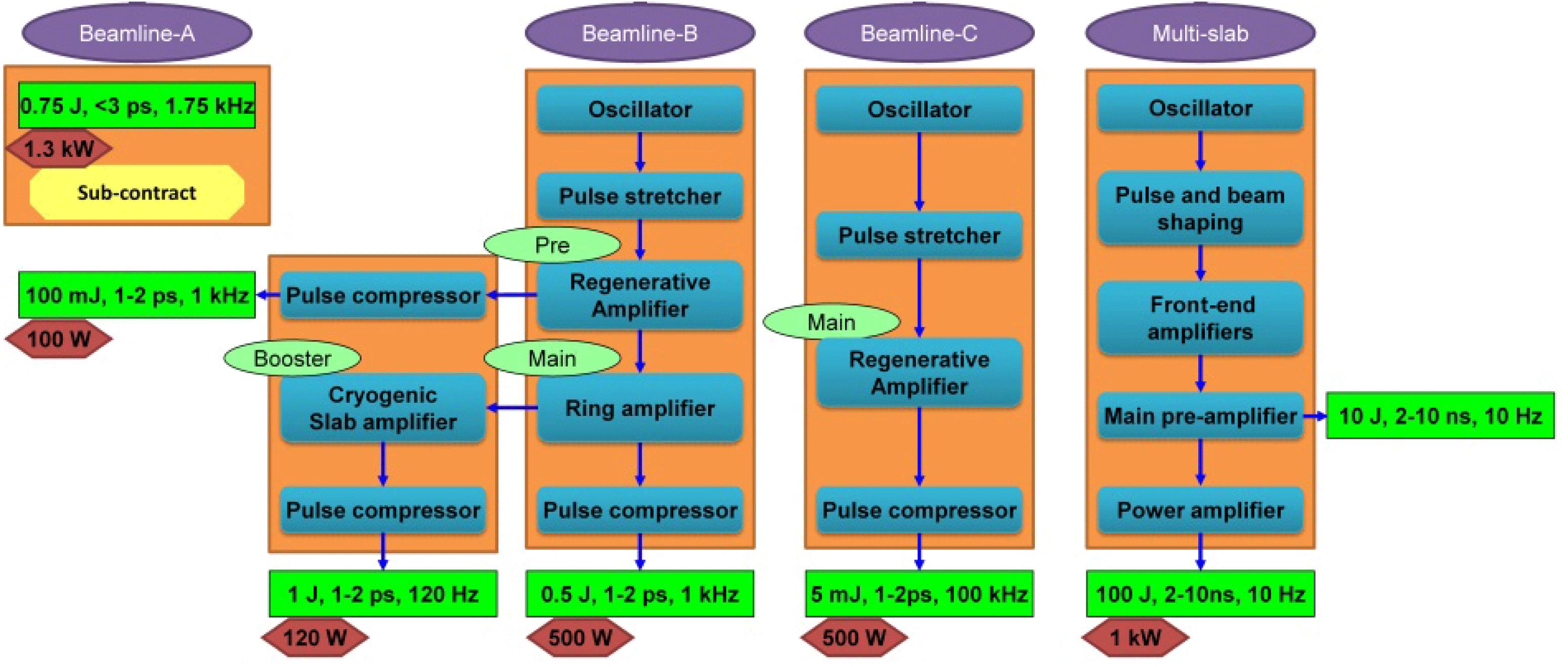
Fig. 2. Overview of the HiLASE beamlines.
Fig. 3. Schematic of the current status of Beamline B. Shown are flat mirrors (M), convex mirrors (XM), concave mirrors (CM), lenses (L), half and quarter waveplates ( ), PBS, and a thin film polarization beam splitter (DP).
), PBS, and a thin film polarization beam splitter (DP). Fig. 4. Schematic of the current status of Beamline C. Shown are an optical isolator (OI),  , PBS, and a CVBG stretcher and compressor.
, PBS, and a CVBG stretcher and compressor. Fig. 5. Schematic of the 100 J multi-slab laser system. The numbers represents the energy after the respective element.
Fig. 6. Schematic of the 10 J cryogenic multi-slab amplifier. It consists of  ceramic slabs in the laser head (Yb:YAG), dichroic beam splitters (DBSs), lens arrays (LAs), vacuum spatial filters (VSFs), and homogenized pump diode laser modules (PDs).
ceramic slabs in the laser head (Yb:YAG), dichroic beam splitters (DBSs), lens arrays (LAs), vacuum spatial filters (VSFs), and homogenized pump diode laser modules (PDs). Fig. 7. Schematic of the 100 J cryogenic multi-slab amplifier. It consists of Yb:YAG, lenses (L), VSF, and PD.
Fig. 8. (a) Schematic of the laser slab with dimensions in mm, dashed line shows the spot of the pump beam in the  part of the slab that is clad by
  . (b) Transverse heat load of the slab used for the calculations (assumed constant in the longitudinal direction).
part of the slab that is clad by . (b) Transverse heat load of the slab used for the calculations (assumed constant in the longitudinal direction). Fig. 9. Measured absorption and emission cross-sections of the  at a temperature of 160 K.
at a temperature of 160 K. Fig. 10. (a) Transverse distribution of temperature and (b) transverse distribution of the  stress component in a longitudinal cut in the center of the laser slab.
stress component in a longitudinal cut in the center of the laser slab. Fig. 11. (a) Depolarization of the beam at the output of the amplifier (after four passes through six laser slabs) caused by stress-induced birefringence. (b) Stress- and temperature-induced OPD after a single pass through the laser head (after one pass through six laser slabs).
Fig. 12. (a) Beam profile and (b) OPD of the beam at the output of the 100 J multi-slab system calculated in MIRÓ. Dashed square indicates the position of the laser beam.
Fig. 13. (a) Output OPD calculated in MIRÓ and shown in Figure 12 (b) after subtraction of tilt and defocus. (b) Residual OPD after correction by the deformable mirror with 36 actuators.
Fig. 14. Schematic of the HiLASE application program.
Fig. 15. Schematic of the LIDT measurement station: (1) high-speed shutter, (2) beam positioning and focus, (3) beam diagnostics, (4) scattered light damage detection and fluorescence collector, (5) slow-motion camera, (6) interference damage detection; (7) XYZ tower, (8) beam dump. It uses laser pulses from Beamline A (L1A), Beamline B (L1B), and the Multi-slab (L2) laser system.
Fig. 16. Schematic of the mid-IR parametric generator and amplifier. It consists of the thin-disk laser system, beam splitters (BS), mirrors (M), dichroic mirrors (DM), an OPG, and OPA.
|
Table 1. Status of kW-class Thin-disk Beamlines.
|
Table 2. Status of kW-class Multi-slab Beamline.


Set citation alerts for the article
Please enter your email address

© Copyright 2018-2021 | Chinese Laser Press. All Rights Reserved 沪ICP备15018463号-20