
M. Divoky, M. Smrz, M. Chyla, P. Sikocinski, P. Severova, O. Novak, J. Huynh, S.S. Nagisetty, T. Miura, J. Pilar, O. Slezak, M. Sawicka, V. Jambunathan, J. Vanda, A. Endo, A. Lucianetti, D. Rostohar, P.D. Mason, P.J. Phillips, K. Ertel, S. Banerjee, C. Hernandez-Gomez, J.L. Collier, and T. Mocek, "Overview of the HiLASE project: high average power pulsed DPSSL systems for research and industry," High Power Laser Sci. Eng. 2, 02000e14 (2014)
- High Power Laser Science and Engineering
- Vol. 2, Issue 2, 02000e14 (2014)
Abstract
1. Introduction
Efficient diode pumping of solid-state lasers (DPSSL) has enabled lasers to reach CW output powers in the region of 100 kW[
In this paper, an overview of the HiLASE activities, including laser development and laser applications, will be presented.
2. Kilowatt-class thin disk laser system
For efficient generation of EUV and mid-IR light, a laser producing several mJ per pulse at a repetition rate of 1–100 kHz is required. For industrial applications, it is important to realize a robust, compact, and low-cost alternative to Ti:sapphire-based pulsed laser systems. Thin-disk lasers with their feature of a high pulse energy in the sub-picosecond region are one of the best devices suited for this application.
Sign up for High Power Laser Science and Engineering TOC. Get the latest issue of High Power Laser Science and Engineering delivered right to you!Sign up now
A thin-disk laser is based on an amplifier concept[ ) laser active medium on a heatsink. The front face of the disk is AR coated, while the back face is HR coated and the disk works as an active mirror. Since the diameter of the disk is much larger than its thickness, the heat flux is mostly axial and the transverse temperature gradient is low. The path of the beam in the disk is short and thermal lens effects and mechanical deformation do not affect the beam quality much. Additionally, a low material path minimizes nonlinear phenomena such as self-focusing.
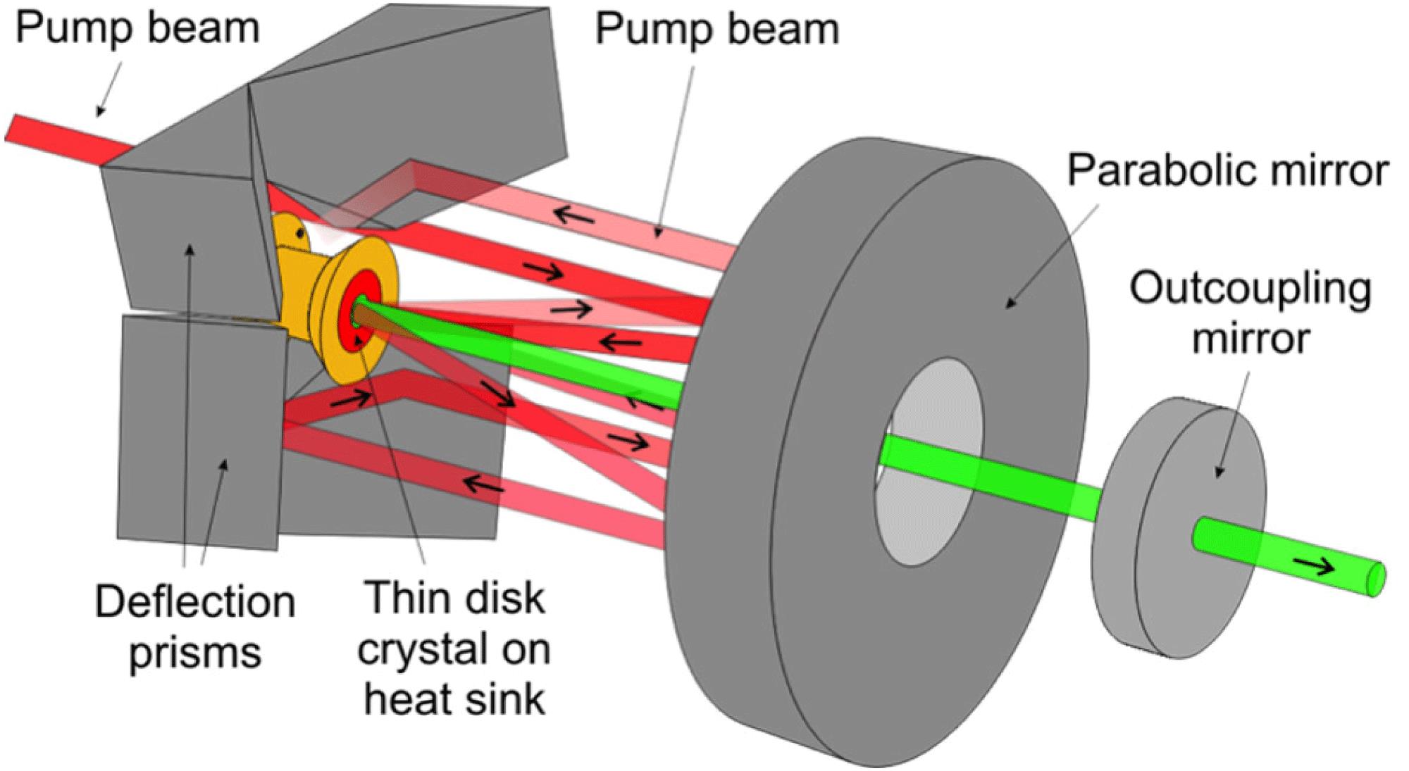
On the other hand, the thinness of the disk causes minimal pump light absorption and laser light gain. Therefore, the number of passes of both pump and laser light must be high. The pump light is sequentially reflected back to the laser disk by a parabolic reflector and roof prisms (Figure
Within the HiLASE project, three thin-disk-based kW-class laser beamlines are being developed, each delivering different output parameters. Beamline A will deliver a 750 mJ pulse energy at a 1.75 kHz repetition rate. This beamline is subcontracted to Dausinger and Giesen GmbH in order to reduce the overall project risk associated with the high demands. The HiLASE research group is developing Beamlines B and C with output parameters of 500 mJ at a 1 kHz repetition rate and 5 mJ at a 100 kHz repetition rate, respectively. All beamlines will provide a pulse duration of 1–3 ps. The output of Beamline B could be diverted into a 10 Hz repetition rate cryogenic amplifier that would later be upgraded to multi-joule output at repetition rates up to 120 Hz. Figure
2.1. Beamline A
Beamline A consists of a fiber front-end that includes a pulse stretcher, pulse picker, and optical isolator. The front-end produces laser pulses with an energy of  at a repetition rate of 1.75 kHz. These pulses are further amplified in a regenerative amplifier to an energy around 150 mJ, then in a linear amplifier to an energy around 0.9 J. The amplified pulses are compressed in a grating pulse compressor to below 3 ps.
2.2. Beamline B
Beamline B[ was employed, providing a group delay dispersion of
  . After the pulse stretching, pulses are coupled into the regenerative amplifier cavity, which contains an
  thin disk, a thin film polarizer (TFP), a Pockels cell with a
  BBO crystal, high-reflection mirrors, and a quarter-wave plate. Pulses from the stretcher are captured in the amplifier cavity when a quarter-wave voltage of more than 10 kV is applied to the Pockels cell, and they travel inside the cavity as long as the high voltage is applied. After amplification, the amplified pulse is ejected through the TFP and passes through an optical isolator consisting of a half-wave plate and a Faraday rotator. Afterwards, the amplified beam is diverted from the input beam by the polarizing beam splitter (PBS) and sent to the pulse compressor. A schematic of the current status of Beamline B is shown in Figure
In order to reduce thermally induced stress between the heatsink and the gain media, CuW is adopted as the heatsink material, because it has similar linear expansion coefficient to YAG. The  crystal, doped to 7 at.%, has thickness of 0.22 mm and is soldered on the CuW heatsink using gold-tin solder. The mounted disk is pumped by a fiber-coupled diode laser module delivering an optical power of up to 1 kW at a wavelength of 969 nm. The pump spot size on the disk was set to 4.8 mm to achieve an output of 45 mJ, and the amplifier cavity was designed so that the cavity mode was matched to the designed pump spot size. The optical-to-optical efficiency was close to 20%. The amplified laser pulses had a bandwidth of 1.5 nm, so they could be compressed down to 1 ps.
The laser cavity will later be upgraded with a second thin-disk head to reach an output energy of 100 mJ. Additionally, the Martinez-type stretcher will be replaced with a fiber-chirped Bragg grating stretcher that allows better control of dispersion and is more stable and compact. Finally, the amplified pulses will be directed to a second regenerative amplifier that will be constructed in 2014.
2.3. Beamline C
Beamline C[ -doped fiber oscillator, as in Beamline B, but the pulses are stretched by a chirped volume Bragg grating (CVBG) up to
  160 ps. The dispersion of the CVBG is
  . The FWHM spectral bandwidth and the clear aperture are
  and
and  , respectively. The dimensions of the BBO crystal for the Pockels cell are
  and its quarter-wave voltage is 5.2 kV. An
  thin-disk with a free aperture of 8 mm and a thickness of
  is installed in the laser head. The disk is pumped by a 1 kW fiber-coupled diode laser module at a wavelength of 969 nm with a pump spot diameter of 2.8 mm. A schematic of the beamline is shown in Figure
The observed output energy was  at a 100 kHz repetition rate. The low pulse energy enabled compression in a highly efficient CVBG compressor. The compressed pulse energy and the efficiency of the CVBG were
  and 88%, respectively. The output pulse had a spectral bandwidth of 1.2 nm and was compressed only to 4 ps pulse duration because the CVBG did not account for the dispersion of material in the path of the beam. By adding an additional diffraction grating compressor, the duration of the compressed pulses was decreased below 2 ps. The output energy will be increased by using more intense pump light and by modifying the thin-disk head and the cavity. Technical difficulties connected to further development of all the mentioned thin-disk beamlines are connected mostly to thermal management of the thin-disk modules and the availability of pump modules at a wavelength of 969 nm.
| Laser system | Beamline A | Beamline B | Beamline C | Cryogenic beamline |
|---|---|---|---|---|
| Completed | Front-end | Regenerative amplifier with one thin-disk head | All, except high power pump modules | None |
| Under development | Regenerative amplifier (May 2014) | Add second thin-disk head into regenerative amplifier | Add high power pump modules | 10 Hz concept amplifier |
| Achieved energy |  | 45 mJ | 0.8 mJ | NA |
| Next milestone energy | 150 mJ | 100 mJ | 2 mJ | 1 J (10 Hz) |
| Final energy | 750 mJ | 500 mJ | 5 mJ | 1 J (100 Hz) |
| Operational | Q2 2015 | Q2 2015 | Q2 2015 | 2016 |
Table 1. Status of kW-class Thin-disk Beamlines.
The current status of thin-disk beamlines is indicated in Table
3. Kilowatt-class multi-slab laser system
To generate high energy pulses at low/moderate repetition rates, it is necessary to adopt an effective cooling mechanism and geometry. One of the solutions is to use an active medium in a slab geometry with active cooling of the slab faces, called a multi-slab, firstly adopted on the Mercury laser at Lawrence Livermore National Laboratory [ ceramic. However,
  is a quasi-three-level system that requires a high pump intensity for laser operation, thus increasing the number and cost of the pumping diodes. By cooling the crystal to low temperatures, the energy scheme changes to four levels, thus decreasing the threshold intensity by several orders of magnitude. Such a concept was introduced by DiPOLE[
The system incorporates a low-energy, fiber-based front end oscillator ( nJ), followed by a regenerative amplifier that increases the output energy to the mJ level and a thin-disk
  multi-pass booster amplifier to raise the output to 100 mJ. Two diode-pumped, helium-gas-cooled large-aperture power amplifiers then increase the output energy to between 7 and 10 J (Main Pre-amplifier) and finally to 100 J (Power Amplifier). The schematic of the system is shown in Figure
3.1. Front end
The front end starts with a temperature-stabilized tunable CW fiber oscillator. The wavelength of the oscillator is matched to the peak of the gain curve of the cryogenically cooled amplifiers. The CW beam is then temporally shaped in an acousto-optic (A-O) modulator to limit the repetition rate to 10 kHz and subsequently shaped by an electro-optic (E-O) modulator to produce 2–10 ns pulses with a semi-triangular shape. The temporal resolution of the shaper is below 200 ps. The pulses are further phase modulated by 2 and 4 GHz modulators to increase the bandwidth of the pulses and prevent stimulated Brillouin scattering (SBS) and stimulated Raman scattering (SRS) in the amplifier chain. Then the repetition of the pulses is decreased by a pulse picker and pulses are amplified in a thin regenerative disk amplifier to  1 mJ. The Gaussian beam coming from the regenerative amplifier is then spatially shaped to a square cross-section super-Gaussian profile in a beam shaper. Then it is further amplified to
  100 mJ in a multi-pass booster amplifier. The booster amplifier preserves the square super-Gaussian beam profile that is injected into the 10 J main pre-amplifier.
3.2. 10 J main pre-amplifer
The 10 J main pre-amplifier is based on a multi-slab design. It consists of four circular  slabs with two doping levels of
  (1.1, 2.0 at.%). The different doping levels are needed to uniformly divide the heat load among the slabs. The volume of each circular slab is diameter in 45 mm with a thickness of 5 mm and the pumped area is square
  . The pump beam is homogenized light from diode stacks operating at 939 nm and producing
  long laser pulses at a repetition rate of 10 Hz. The
  is clad with a 5 mm
  absorber (absorption coefficient
  ) that prevents amplified spontaneous emission (ASE) and parasitic oscillations. The amplifier is cooled by forced helium gas flow and operates between 150 and 170 K.
The extraction scheme of the multi-pass amplifier is shown in Figure  ) to a back reflector and back to the amplifier head. There is one spatial filter on each side of the amplifier head. Each pass is propagated by a set of separate mirrors. A deformable mirror is placed in the amplifier after the third pass. After seven or eight passes, the beam is ejected from the amplifier with a pulse energy of 7 J in the beam and a size of
  .
.
3.3. 100 J power amplifier
The 100 J power amplifier is also based on the multi-slab design. It consists of six square  slabs with three doping levels of
  (0.4, 0.6, 1.0 at.%). The volume of each slab is
  and the square pumped area is around
  . The parameters of the pump light are similar to the 10 J amplifier. The
  is clad with a 10 mm wide
  absorber (absorption coefficient
  ) that prevents ASE and parasitic oscillations.
The extraction scheme of the multi-pass amplifier is shown in Figure  , so any overlap with the pump beam outside the amplifier head is avoided and no dichroic mirrors are used. Each additional pass is image-relayed by a dedicated spatial filter (
 ) back to the amplifier head. After the first pass, a deformable mirror is implemented to prevent degradation of the wavefront on subsequent passes. After four passes, the beam is ejected from the amplifier with a pulse energy of up to 120 J and a beam size around
  . The average fluence in the amplified beam is
  . The amplifier is cooled by forced helium gas flow and operates between 150 and 170 K.
The current status of the multi-slab laser system is indicated in Table
| Laser system | Beamline A |
|---|---|
| Completed | 10 J main pre-amplifier |
| Under development | 100 J power amplifier |
| Achieved energy | 10 J |
| Next milestone energy | 50 J |
| Final energy | 100 J |
| Operational | Q3 2015 |
Table 2. Status of kW-class Multi-slab Beamline.
3.4. Numerical modeling
The HiLASE team has undertaken extensive energetics, thermal and fluid-mechanical modeling in order to optimize various amplifier parameters.
For energetics modeling, we have developed a MATLAB code[ laser slabs by solving the rate equations in discrete time steps. During each step, the absorption of the pump radiation and spontaneous emission are calculated independently. In the absorption phase, the energy from a polychromatic pump source is absorbed in the medium in accordance with a probability proportional to the number of unexcited active ions and the absorption cross-section dependent on the pump wavelength. In the ASE phase, spontaneously emitted photons with random polarization are generated by the Monte Carlo method using the excited ion density inside the slab as the probability distribution. Their wavelength distribution is based on a probability density function derived from the emission cross-section. Rays containing thousands of photons are traced through the medium and amplified proportionally to the population inversion and the path length in each cell. All slabs of the amplifier are included in the model so the propagation of the rays among the slabs can be modeled. All surfaces can be treated as Fresnel reflecting, AR coated, or absorbing. Side faces can also include scattering. The slab model includes the active
  core and the absorbing
  cladding. A schematic of the slab and the calculated heat deposition are shown in Figure
  , pump size
  ,
,  cladding 10 mm, absorption coefficient
  , pump duration 1 ms, intensity
  , and temperature 160 K.
The wavelength-resolved absorption and emission cross-sections and lifetime on the upper laser level for a given temperature were obtained experimentally [ at a temperature of 160 K is shown in Figure
A three-dimensional finite-element method (FEM) using Comsol Multiphysics software was chosen to model the thermal and stress effects in the amplifiers. The sources of heat were calculated in the ASE code. The lateral surfaces of the slabs are assumed to be cooled by flowing helium gas at 160 K. The spatially resolved heat transfer coefficient was derived from a two-dimensional model of a turbulent flow of helium gas at 160 K using the standard  model[
A beam propagation model of the 100 J power amplifier was created in MIRÓ using a Fresnel diffraction integral for propagation and the Frantz–Nodvik equation for amplification. The model was used to estimate beam aberrations, taking into consideration only the thermal OPD. The results of the beam intensity and OPD are shown in Figure
The numerical model for wavefront correction calculates influence functions from a plate equation describing the bending of the thin facesheet for each individual actuator of the deformable mirror. The deformable mirror consists of a continuous gold facesheet (size of  , thickness of 1 mm) on which lateral forces are applied by piezoelectric stack actuators. The actuators form an equidistantly spaced rectangular array of
  actuators and are capable of push/pull operation. The deformation of the mirror is computed as a superposition of the influence functions and the algorithm minimizes the rms OPD value.
The OPD after subtraction of defocus and tilt and the OPD corrected by the deformable mirror are shown in Figure
4. Applications
One of the long-term objectives of HiLASE is the identification of new and promising industrial applications and technologies using the DPSSL systems that were described above. Once commissioned in the HiLASE center these advanced DPSSL systems will enable, for example, research relevant to the testing of new dielectric optical components with high damage thresholds, prototyping new pump lasers for OPCPA (Optical Parametric Chirped Pulse Amplification) systems, driving high yield secondary photon and particle sources, and industrial applications related to efficient processing of materials (ablative removal of thin layers, cutting of optically transparent materials, laser peening, surface structuring and modifications, etc.). An overview of the HiLASE laser application program is shown in Figure
4.1. Laser-induced damage threshold testing
First, the laser-induced damage threshold (LIDT) automated experimental station would be introduced. The station design allows one to measure the LIDT under a wide range of laser parameters: from the irradiation of small spots with 1–2 ps laser pulses at various wavelengths and a 1 kHz repetition rate to the irradiation of large spots with 2–10 ns laser pulses at 1030 nm with a 10 Hz repetition rate. The main advantage of this station is real-time monitoring of laser damage with an acquisition frequency of up to 1 kHz. This station will allow the determination of the damage occurrence, as well as following the damage growth and damage threshold variation under repetitive irradiation. A schematic of the station is shown in Figure  .
.
4.2. Mid-IR optical parametric generator
For the investigation of laser–material interactions and processing, as well as the thin-disk and multi-slab systems, a mid-IR pulse source with a high repetition rate and an average power of 10 W [ . Only the signal beam is amplified by the optical parametric amplifier (OPA) chain. Idler beams having wavelengths from 2 to
  can be extracted from the last parametric amplifier.
4.3. EUV light generation
For EUV generation, powerful  lasers are used to evaporate tin (Sn) droplets to generate a plasma that emits light at 13.5 nm. The
  laser provides a much higher average power and higher conversion efficiency to UV light, but the laser footprint and plasma size are large[
 lasers but at the same time the average power output required is only in the region of 1 kW. For this reason, we are constructing an EUV generation station using a thin-disk amplifier with a high average power. This source will be employed to study processes during EUV light generation.
References
[1] E. Shcherbakov, V. Fomin, A. Abramov, A. Ferin, D. Mochalov, V. P. GapontsevAdvanced Solid-State Lasers Congress.
[4] C. Y. Teisset, M. Schultze, R. Bessing, M. Häfner, S. Prinz, D. Sutter, T. MetzgerAdvanced Solid-State Lasers Congress.
[5] R. Jung, J. Tümmler, Th. Nubbemeyer, I. Will, W. Sandner, G. Erbert, W. Pittroff2nd Disk Laser Workshop.
[9] M. Divoky, S. Tokita, H. Furuse, K. Matsumoto, Y. Nakamura, J. KawanakaAdvanced Solid-State Lasers Congress.
[13] A. Giesen, H. Hugel, A. Voss, K. Wittig, U. Brauch, H. Opower. Appl. Phys. B, 58, 365(1994).
[16] M. Smrz, T. Miura, M. Chyla, A. Endo, T. MocekIEEE Photonics Conference.
[19] P. D. Mason, K. Ertel, S. Banerjee, P. Phillips, C. Hernandez-Gomez, J. Collier. Proc. SPIE, 8780, 87801X(2013).
[22] B. E. Launder, D. B. Spalding. Comput. Meth. Appl. Mech. Eng., 3, 269(1974).
[23] W. M. Kays. Convective Heat and Mass Transfer(1993).
[24] H. Schlichting, K. Gersten. Boundary Layer Theory(2000).
[27] O. Novak, T. Miura, P. Severova, M. Smrž, A. Endo, T. MocekAdvanced Solid-State Lasers Congress.
[28] A. EndoSource: Lithography.


Set citation alerts for the article
Please enter your email address

© Copyright 2018-2021 | Chinese Laser Press. All Rights Reserved 沪ICP备15018463号-20