• Photonics Research
  • Vol. 10, Issue 5, 1177 (2022)
Aroutin Khachaturian*, Reza Fatemi, Artsroun Darbinian, and Ali Hajimiri
Author Affiliations
  • California Institute of Technology, Pasadena, California 91125, USA
  • show less
    DOI: 10.1364/PRJ.443061 Cite this Article Set citation alerts
    Aroutin Khachaturian, Reza Fatemi, Artsroun Darbinian, Ali Hajimiri. Discretization of annular-ring diffraction pattern for large-scale photonics beamforming[J]. Photonics Research, 2022, 10(5): 1177 Copy Citation Text show less
    Diffraction pattern of circularly symmetric apertures with diameter D=2λ when illuminated by a plane wave. (a) Circular aperture. (b) Annular-ring aperture. (c) Discretization of the annular ring with 25 points. G≈λ/2 is the arc-length distance between two elements. (d) Diffraction pattern cross-section of apertures in (a), (b), and (c). (e) Generalization of discretized multi-annular-ring apertures equivalent to circular-grid phased arrays.
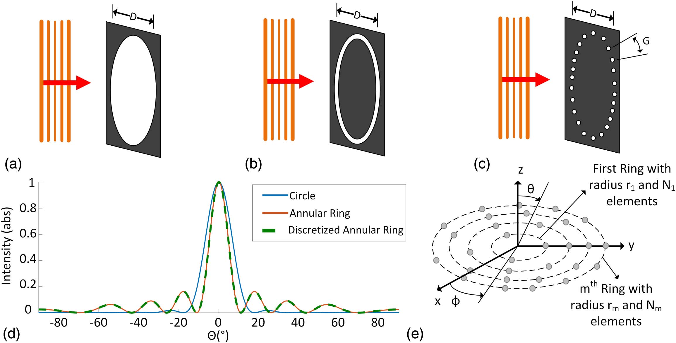
    Fig. 1. Diffraction pattern of circularly symmetric apertures with diameter D=2λ when illuminated by a plane wave. (a) Circular aperture. (b) Annular-ring aperture. (c) Discretization of the annular ring with 25 points. Gλ/2 is the arc-length distance between two elements. (d) Diffraction pattern cross-section of apertures in (a), (b), and (c). (e) Generalization of discretized multi-annular-ring apertures equivalent to circular-grid phased arrays.
    (a) Effect of annular-ring discretization on the far-field array factor. A 20 μm diameter ring is plotted for a continuous annular-ring-slit aperture (or half wavelength-spacing elements), discretized with 40 isotropic radiators and 20 isotropic radiators. (b) Beamwidth and 3 dB beam efficiency trends as a function of phased array aperture diameter. (c) Minimum beamwidth as a function of 3 dB beam efficiency for linear density multi-annular-ring OPAs at the planar routing limits for single-layer and two-layer photonics process. (d) SLL and effective aperture as a function of aperture diameter.
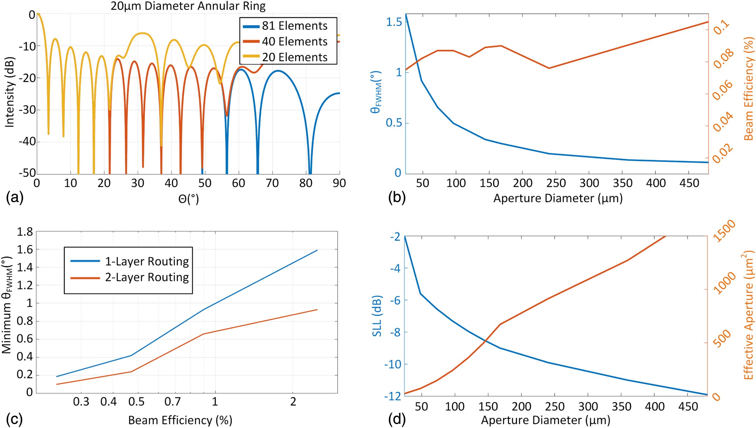
    Fig. 2. (a) Effect of annular-ring discretization on the far-field array factor. A 20 μm diameter ring is plotted for a continuous annular-ring-slit aperture (or half wavelength-spacing elements), discretized with 40 isotropic radiators and 20 isotropic radiators. (b) Beamwidth and 3 dB beam efficiency trends as a function of phased array aperture diameter. (c) Minimum beamwidth as a function of 3 dB beam efficiency for linear density multi-annular-ring OPAs at the planar routing limits for single-layer and two-layer photonics process. (d) SLL and effective aperture as a function of aperture diameter.
    Multi-annular-ring aperture OPA system. Die photo of the proposed design and SEM photo of the aperture. Phase and amplitude modulators are grouped into four blocks for symmetric layout.
    Fig. 3. Multi-annular-ring aperture OPA system. Die photo of the proposed design and SEM photo of the aperture. Phase and amplitude modulators are grouped into four blocks for symmetric layout.
    (a) Layout and signal distribution for a 255-element annular-ring aperture. (b) Full AF of the aperture for ϕ=0, including the radiator’s beam pattern. (c) Custom radiating element used in this OPA. (d) The far-field radiation pattern of the radiating element.
    Fig. 4. (a) Layout and signal distribution for a 255-element annular-ring aperture. (b) Full AF of the aperture for ϕ=0, including the radiator’s beam pattern. (c) Custom radiating element used in this OPA. (d) The far-field radiation pattern of the radiating element.
    Row–column drive scheme for amplitude and phase modulators. (a) Four out of 16 rows from the 16×9 row–column block. The elements in each row are programmed by forward-biasing the elements in that row while keeping all the other rows in reverse bias. Each row is active for T/16 of the programming cycle and programs all 16 elements in each row. (b) Implemented phase modulator using a compact spiral thermo-optic modulator. (c) Implemented amplitude modulator based on a tunable MZI splitter using a compact spiral modulator.
    Fig. 5. Row–column drive scheme for amplitude and phase modulators. (a) Four out of 16 rows from the 16×9 row–column block. The elements in each row are programmed by forward-biasing the elements in that row while keeping all the other rows in reverse bias. Each row is active for T/16 of the programming cycle and programs all 16 elements in each row. (b) Implemented phase modulator using a compact spiral thermo-optic modulator. (c) Implemented amplitude modulator based on a tunable MZI splitter using a compact spiral modulator.
    Tunable amplitude modulation with calibration feedback. (a) Unit tunable power splitter with 1% sniffer output for control. (b) 1:8 tunable power splitter with reduced sensing interconnect complexity.
    Fig. 6. Tunable amplitude modulation with calibration feedback. (a) Unit tunable power splitter with 1% sniffer output for control. (b) 1:8 tunable power splitter with reduced sensing interconnect complexity.
    (a) Beam power optimization progression after 450 iterations. (b) Dynamic stability and repeatability of the annular-ring OPA. The PAM drivers can maintain the optimized setting with less than 0.4 dB variations.
    Fig. 7. (a) Beam power optimization progression after 450 iterations. (b) Dynamic stability and repeatability of the annular-ring OPA. The PAM drivers can maintain the optimized setting with less than 0.4 dB variations.
    2D beamforming demonstration. (a) 2D beam pattern was measured for the optimized direction (0°, 0°). (b) 1D cross-sections of the beam pattern in θx (ϕ=0° plane). (c) 1D cross-sections of the beam pattern in θy (ϕ=90° plane).
    Fig. 8. 2D beamforming demonstration. (a) 2D beam pattern was measured for the optimized direction (0°, 0°). (b) 1D cross-sections of the beam pattern in θx (ϕ=0° plane). (c) 1D cross-sections of the beam pattern in θy (ϕ=90° plane).
    Cross-sectional view of the beam pattern for several directions. (a) Phase-shifter-enabled beam steering in θx (ϕ=0° plane) for two additional directions. (b) Phase-shifter-enabled beam steering in θy (ϕ=90° plane) for an additional direction.
    Fig. 9. Cross-sectional view of the beam pattern for several directions. (a) Phase-shifter-enabled beam steering in θx (ϕ=0° plane) for two additional directions. (b) Phase-shifter-enabled beam steering in θy (ϕ=90° plane) for an additional direction.
     This WorkCaltech 2019 [29]Caltech 2018 [6]USC 2015 [27]UPenn 2019 [7]KIAST 2019 [2]NUAA 2018 [21]
    Aperture TypeUniform polarSparse CartesianUniform CartesianUniform CartesianUniform CartesianUniform Cartesian, MEMSNonuniform polar
    Number of Radiators (N)2551288×88×88×8160×16073
    Beamwidtha0.8°0.75°0.45°N/Ab0.04°×0.03°N/A
    SLL4  dBa12  dB10  dB11  dBN/A11/18  dB11  dBc
    Steering Range23°×16.3°16°1.6°6.6°×4.4°30°
    Number of Maximum Resolvable Spots (S)9315c40011312N/A25,600N/A
    Number of Drivers100326412916N/AN/A
    Table 1. Comparison of Recent 2D Aperture OPAs
    Aroutin Khachaturian, Reza Fatemi, Artsroun Darbinian, Ali Hajimiri. Discretization of annular-ring diffraction pattern for large-scale photonics beamforming[J]. Photonics Research, 2022, 10(5): 1177
    Download Citation