• Photonics Research
  • Vol. 6, Issue 11, 1084 (2018)
Evgeni A. Bezus1、2、*, Dmitry A. Bykov1、2, and Leonid L. Doskolovich1、2
Author Affiliations
  • 1Image Processing Systems Institute—Branch of the Federal Scientific Research Centre “Crystallography and Photonics” of the Russian Academy of Sciences, 151 Molodogvardeyskaya St., Samara 443001, Russia
  • 2Samara National Research University, 34 Moskovskoe Shosse, Samara 443086, Russia
  • show less
    DOI: 10.1364/PRJ.6.001084 Cite this Article Set citation alerts
    Evgeni A. Bezus, Dmitry A. Bykov, Leonid L. Doskolovich. Bound states in the continuum and high-Q resonances supported by a dielectric ridge on a slab waveguide[J]. Photonics Research, 2018, 6(11): 1084 Copy Citation Text show less
    (a) Geometry of the considered integrated structure. I, R, and T denote the incident, reflected, and transmitted TE-polarized guided modes, respectively. (b) 2D effective index model and corresponding refractive indices.
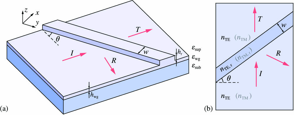
    Fig. 1. (a) Geometry of the considered integrated structure. I, R, and T denote the incident, reflected, and transmitted TE-polarized guided modes, respectively. (b) 2D effective index model and corresponding refractive indices.
    (a) Reflectance and (b) transmittance of the TE-polarized mode versus the angle of incidence θ and ridge width w. Horizontal dashed lines show the cutoff angles θsup, θsub, θTM, and θTM,r. Field distributions in the structure at the points marked with asterisks in (a) are shown in Fig. 3. Dashed red curves in (b) show the dispersion of quasi-TM modes calculated using the approximate Eq. (4). (c) Reflectance and (d) transmittance of a plane wave upon refraction by a thin film (effective index model) are also shown.
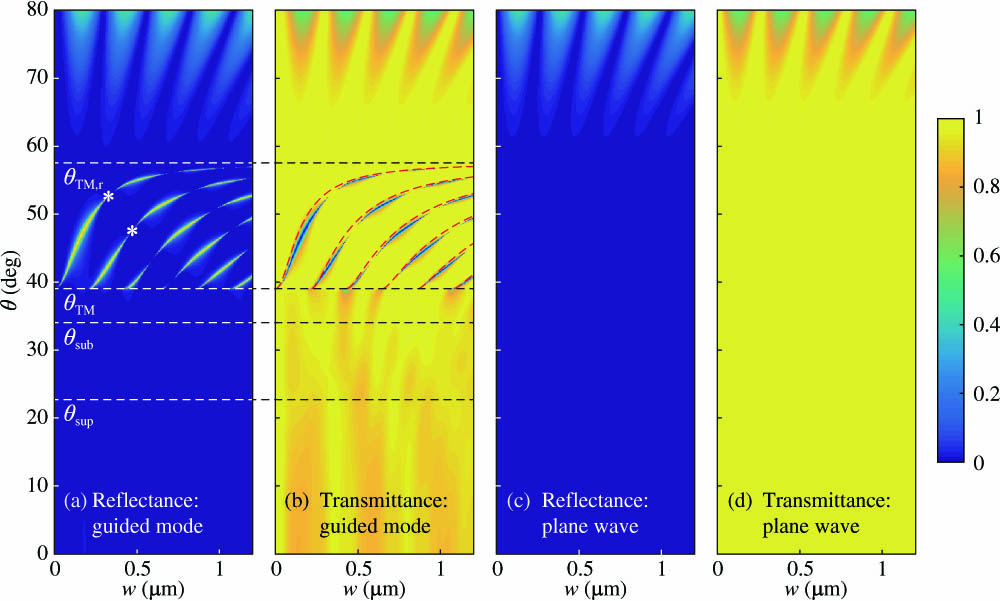
    Fig. 2. (a) Reflectance and (b) transmittance of the TE-polarized mode versus the angle of incidence θ and ridge width w. Horizontal dashed lines show the cutoff angles θsup, θsub, θTM, and θTM,r. Field distributions in the structure at the points marked with asterisks in (a) are shown in Fig. 3. Dashed red curves in (b) show the dispersion of quasi-TM modes calculated using the approximate Eq. (4). (c) Reflectance and (d) transmittance of a plane wave upon refraction by a thin film (effective index model) are also shown.
    Electric field distributions in the structure at resonance conditions: (a) w=326 nm, θ=52.66°; (b) w=470 nm, θ=47.58°.
    Fig. 3. Electric field distributions in the structure at resonance conditions: (a) w=326  nm, θ=52.66°; (b) w=470  nm, θ=47.58°.
    (a) Magnified fragment of the rigorously calculated reflectance spectrum shown in Fig. 2(a). Red dashed curves show mode dispersion obtained from the model in Section 4 using Eq. (12). (w,θ) points shown with white circles and black crosses were obtained from Eqs. (18) and (16). White circles predict the BIC locations, whereas black crosses correspond to the “low-Q” resonances. (b) Model reflectance spectrum |R|2 calculated using Eq. (8).
    Fig. 4. (a) Magnified fragment of the rigorously calculated reflectance spectrum shown in Fig. 2(a). Red dashed curves show mode dispersion obtained from the model in Section 4 using Eq. (12). (w,θ) points shown with white circles and black crosses were obtained from Eqs. (18) and (16). White circles predict the BIC locations, whereas black crosses correspond to the “low-Q” resonances. (b) Model reflectance spectrum |R|2 calculated using Eq. (8).
    Rigorously calculated (a) excitation angle θ and (b) quality factor Q of the mode versus ridge width w. (c) Angular reflectance spectra of the structure at different ridge widths. Red line shows the spectrum of the structure supporting a BIC. Black points in (b) and (c) depict the BIC location.
    Fig. 5. Rigorously calculated (a) excitation angle θ and (b) quality factor Q of the mode versus ridge width w. (c) Angular reflectance spectra of the structure at different ridge widths. Red line shows the spectrum of the structure supporting a BIC. Black points in (b) and (c) depict the BIC location.
    Plane wave diffraction by a slab supporting two cross-polarized waves coupled at the interfaces.
    Fig. 6. Plane wave diffraction by a slab supporting two cross-polarized waves coupled at the interfaces.
    Evgeni A. Bezus, Dmitry A. Bykov, Leonid L. Doskolovich. Bound states in the continuum and high-Q resonances supported by a dielectric ridge on a slab waveguide[J]. Photonics Research, 2018, 6(11): 1084
    Download Citation