
Jian Luo, Jie Song, Sijun Fang, Fanle Kong, Yong Yan. Decoupling study and noise analysis of multi-degree-of-freedom deformation measurement method for space gravitational wave detection telescope[J]. Opto-Electronic Engineering, 2024, 51(2): 230211
- Opto-Electronic Engineering
- Vol. 51, Issue 2, 230211 (2024)
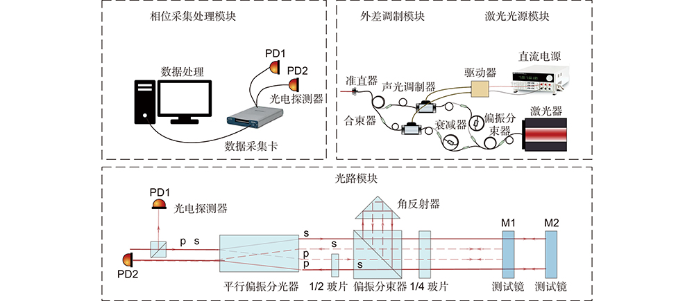
Fig. 1. Schematic diagram of the composition of a three-degree-of-freedom deformation measurement system
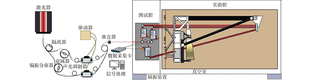
Fig. 2. Schematic diagram of the three-degree-of-freedom deformation measurement system
Fig. 3. Schematic diagram of measurement point position selection
Fig. 4. Schematic diagram of the decoupling mathematical model for the three-degree-of-freedom deformation measurement system
Fig. 5. Zemax optical system simulation
Fig. 6. Relationship between displacement and phase
Fig. 7. (a) Schematic diagram of the actual measurement path; (b) Zemax optical path modeling diagram
Fig. 8. Laser frequency noise background
Fig. 9. Laboratory temperature and vibration level. (a) Temperature test chart; (b) Vibration test chart
Fig. 10. NI data acquisition card noise background
Fig. 11. Photodetector noise background
Fig. 12. Background noise of the single chain interferometer
| ||||||||||||||||||||
Table 1. Advantages and disadvantages of multiple-degree-of-freedom measurement methods
| |||||||||||||||||||||||
Table 2. Test the relationship between the rigid body displacement of the mirror and the phase difference received by the photodetector
|
Table 3. Error sensitivity analysis of the measurement system with multiple degrees of freedom
| ||||||||||||||||||||||||||||||||||||||||||
Table 4. Allocation and requirements of optical path noise indicators for the telescope deformation measurement system

Set citation alerts for the article
Please enter your email address
© Copyright 2018-2021 | Chinese Laser Press. All Rights Reserved 沪ICP备15018463号-20