• Photonics Research
  • Vol. 10, Issue 5, 1280 (2022)
Tengfei Hao1、2、3、†, Hao Ding4、†, Wei Li1、2、3, Ninghua Zhu1、2、3, Yitang Dai4、5、6, and Ming Li1、2、3、*
Author Affiliations
  • 1State Key Laboratory on Integrated Optoelectronics, Institute of Semiconductors, Chinese Academy of Sciences, Beijing 100083, China
  • 2School of Electronic, Electrical and Communication Engineering, University of Chinese Academy of Sciences, Beijing 100049, China
  • 3Center of Materials Science and Optoelectronics Engineering, University of Chinese Academy of Sciences, Beijing 100190, China
  • 4State Key Laboratory of Information Photonics and Optical Communications, Beijing University of Posts and Telecommunications, Beijing 100876, China
  • 5Peng Cheng Laboratory, Shenzhen 518052, China
  • 6e-mail: ytdai@bupt.edu.cn
  • show less
    DOI: 10.1364/PRJ.451109 Cite this Article Set citation alerts
    Tengfei Hao, Hao Ding, Wei Li, Ninghua Zhu, Yitang Dai, Ming Li. Dissipative microwave photonic solitons in spontaneous frequency-hopping optoelectronic oscillators[J]. Photonics Research, 2022, 10(5): 1280 Copy Citation Text show less
    Schematic diagram and operating principle of the spontaneous frequency-hopping soliton OEO. (a) Schematic diagram. A dual-passband filter is used to select two groups of interacting cavity modes. Spontaneous frequency hopping is related to the formation of dissipative microwave photonic solitons due to the interaction between the two groups of modes. (b) Principle of the dissipative microwave photonic solitons. (c) Illustration of the dissipative microwave photonic solitons and the corresponding frequency-hopping microwave signal. The dissipative microwave photonic solitons are the product of wave packets of the two groups of interacting oscillation modes. The solitons maintain their shape due to the double balance between nonlinear gain saturation and linear filtering as well as cavity loss and gain, creating frequency-hopping microwave signals. Whenever a soliton occurs, frequency hopping occurs. (d) Experimental setup. A dual-passband MPF is implemented based on PM-IM conversion using a PM and a dual-passband optical notch filter. (e) Principle of the MPF. The shape of the MPF in the microwave domain is the reverse shape of the optical notch filter in the optical domain, where fc is the frequency of the LD; f1 and f2 are the center frequencies of the two passbands of the MPF. MPF, microwave photonic filter; E/O, electrical to optical conversion; O/E, optical to electrical conversion; LD, laser diode; PM, phase modulator; EDFA, erbium-doped fiber amplifier; PD, photodetector; EA, electrical amplifier.
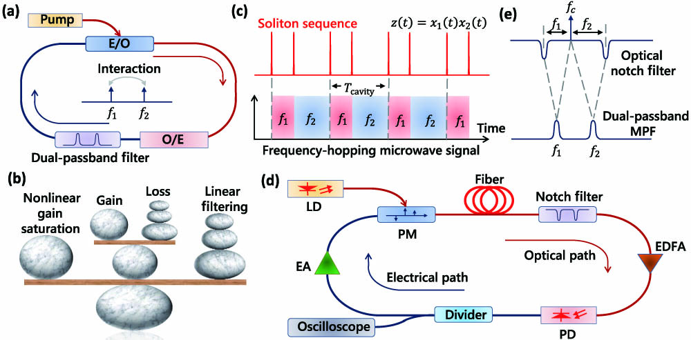
    Fig. 1. Schematic diagram and operating principle of the spontaneous frequency-hopping soliton OEO. (a) Schematic diagram. A dual-passband filter is used to select two groups of interacting cavity modes. Spontaneous frequency hopping is related to the formation of dissipative microwave photonic solitons due to the interaction between the two groups of modes. (b) Principle of the dissipative microwave photonic solitons. (c) Illustration of the dissipative microwave photonic solitons and the corresponding frequency-hopping microwave signal. The dissipative microwave photonic solitons are the product of wave packets of the two groups of interacting oscillation modes. The solitons maintain their shape due to the double balance between nonlinear gain saturation and linear filtering as well as cavity loss and gain, creating frequency-hopping microwave signals. Whenever a soliton occurs, frequency hopping occurs. (d) Experimental setup. A dual-passband MPF is implemented based on PM-IM conversion using a PM and a dual-passband optical notch filter. (e) Principle of the MPF. The shape of the MPF in the microwave domain is the reverse shape of the optical notch filter in the optical domain, where fc is the frequency of the LD; f1 and f2 are the center frequencies of the two passbands of the MPF. MPF, microwave photonic filter; E/O, electrical to optical conversion; O/E, optical to electrical conversion; LD, laser diode; PM, phase modulator; EDFA, erbium-doped fiber amplifier; PD, photodetector; EA, electrical amplifier.
    Soliton sequence and spontaneous frequency-hopping microwave signal for a 20-MHz MPF. (a) Soliton sequence. The dissipative microwave photonic solitons are periodic; there are two soliton pulses per cavity round-trip time. The two soliton pulses are marked as s1 and s2 to distinguish them. The magnified view shows the details of the generated solitons with a pulse width of 43 ns. (b) Calculated instantaneous frequency-time diagram of the spontaneous frequency-hopping microwave signal. Frequency hopping occurs when a soliton is formed. (c) Temporal waveform of the spontaneous frequency-hopping microwave signal. The two groups of modes have slightly different amplitudes. (d) Details of the temporal waveform when frequency hopping occurs. The cavity modes are switched from one to the other within tens of nanoseconds. The frequency-hopping speed is similar to the soliton pulse width. (e) Spectrum of the spontaneous frequency-hopping microwave signal. (f) Measured frequency response of the 20-MHz MPF.
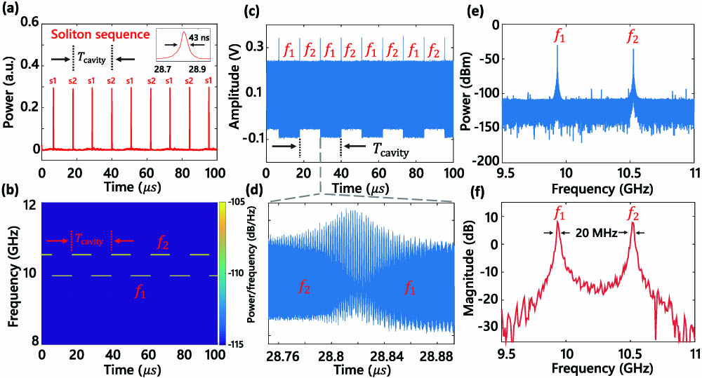
    Fig. 2. Soliton sequence and spontaneous frequency-hopping microwave signal for a 20-MHz MPF. (a) Soliton sequence. The dissipative microwave photonic solitons are periodic; there are two soliton pulses per cavity round-trip time. The two soliton pulses are marked as s1 and s2 to distinguish them. The magnified view shows the details of the generated solitons with a pulse width of 43 ns. (b) Calculated instantaneous frequency-time diagram of the spontaneous frequency-hopping microwave signal. Frequency hopping occurs when a soliton is formed. (c) Temporal waveform of the spontaneous frequency-hopping microwave signal. The two groups of modes have slightly different amplitudes. (d) Details of the temporal waveform when frequency hopping occurs. The cavity modes are switched from one to the other within tens of nanoseconds. The frequency-hopping speed is similar to the soliton pulse width. (e) Spectrum of the spontaneous frequency-hopping microwave signal. (f) Measured frequency response of the 20-MHz MPF.
    Tuning of the spontaneous frequency-hopping soliton OEO. The frequency-hopping speed, frequency, period, and frequency-hopping number can be tuned. (a) Generated soliton sequence for a 50-MHz MPF. (b) Details of the soliton sequence. Blue dashed line: simulation result. Red line: experimental result. The pulse width is about 18 ns, which is shorter than that of the 20-MHz MPF because of the reduction in the linear filtering effect. (c) Calculated instantaneous frequency-time diagram of the spontaneous frequency-hopping microwave signal. (d) Soliton pulse width for different gains and filter bandwidths. Δf is the 3-dB bandwidth of the filter and the gray circles with up or down arrows represent the x axis of the data, i.e., the gain or the filter bandwidth, respectively. The soliton pulse and the frequency-hopping speed can be tuned by changing the cavity gain or filter bandwidth. (e) Instantaneous frequency-time diagram of the generated microwave signal with different frequencies and repetition rates. (f) Instantaneous frequency-time diagram of the generated microwave signal with different frequencies and frequency-hopping numbers.
    Fig. 3. Tuning of the spontaneous frequency-hopping soliton OEO. The frequency-hopping speed, frequency, period, and frequency-hopping number can be tuned. (a) Generated soliton sequence for a 50-MHz MPF. (b) Details of the soliton sequence. Blue dashed line: simulation result. Red line: experimental result. The pulse width is about 18 ns, which is shorter than that of the 20-MHz MPF because of the reduction in the linear filtering effect. (c) Calculated instantaneous frequency-time diagram of the spontaneous frequency-hopping microwave signal. (d) Soliton pulse width for different gains and filter bandwidths. Δf is the 3-dB bandwidth of the filter and the gray circles with up or down arrows represent the x axis of the data, i.e., the gain or the filter bandwidth, respectively. The soliton pulse and the frequency-hopping speed can be tuned by changing the cavity gain or filter bandwidth. (e) Instantaneous frequency-time diagram of the generated microwave signal with different frequencies and repetition rates. (f) Instantaneous frequency-time diagram of the generated microwave signal with different frequencies and frequency-hopping numbers.
    Simulation results when a 50-MHz dual-passband filter is used in the frequency-hopping soliton OEO. (a) Soliton sequence. (b) Instantaneous frequency-time diagram of the spontaneous frequency-hopping microwave signal. (c) Temporal waveform. (d) Details of the temporal waveform when frequency hopping occurs.
    Fig. 4. Simulation results when a 50-MHz dual-passband filter is used in the frequency-hopping soliton OEO. (a) Soliton sequence. (b) Instantaneous frequency-time diagram of the spontaneous frequency-hopping microwave signal. (c) Temporal waveform. (d) Details of the temporal waveform when frequency hopping occurs.
    Frequency-hopping and soliton sequence in a different OEO structure, demonstrating the universality of the spontaneous frequency-hopping phenomenon in soliton OEOs. (a) Schematic diagram. An optical bandpass filter instead of a dual-passband filter is used in the optical path. The joint use of the PM and optical bandpass filter corresponds to a broadband MPF. (b) Measured open-loop response of the OEO. Only the gain of the two groups of interacting modes is above threshold; thus, two groups of interacting modes can be selected by the broadband MPF. (c) Temporal waveform of the spontaneous frequency-hopping microwave signal. (d) Corresponding soliton sequence. (e) Instantaneous frequency-time diagram of the frequency-hopping microwave signal.
    Fig. 5. Frequency-hopping and soliton sequence in a different OEO structure, demonstrating the universality of the spontaneous frequency-hopping phenomenon in soliton OEOs. (a) Schematic diagram. An optical bandpass filter instead of a dual-passband filter is used in the optical path. The joint use of the PM and optical bandpass filter corresponds to a broadband MPF. (b) Measured open-loop response of the OEO. Only the gain of the two groups of interacting modes is above threshold; thus, two groups of interacting modes can be selected by the broadband MPF. (c) Temporal waveform of the spontaneous frequency-hopping microwave signal. (d) Corresponding soliton sequence. (e) Instantaneous frequency-time diagram of the frequency-hopping microwave signal.
    Comparison of the phase noise performance of the soliton OEO and an electrical frequency-hopping source. The soliton OEO provides lower phase noise by using a long optical fiber and a narrowband filter. The phase noise of the soliton OEO is as low as −133.1 dBc/Hz at 10-kHz offset frequency, which is 38-dB lower than that of the electrical frequency-hopping source.
    Fig. 6. Comparison of the phase noise performance of the soliton OEO and an electrical frequency-hopping source. The soliton OEO provides lower phase noise by using a long optical fiber and a narrowband filter. The phase noise of the soliton OEO is as low as 133.1  dBc/Hz at 10-kHz offset frequency, which is 38-dB lower than that of the electrical frequency-hopping source.
    Temporal waveform of the frequency-hopping soliton OEO during 9000 round trips. Sub-Nyquist sampling with a sampling rate of 62.5 MS/s is used. The total time duration is 200 ms. The frequency-hopping signal is stable after thousands of round trips.
    Fig. 7. Temporal waveform of the frequency-hopping soliton OEO during 9000 round trips. Sub-Nyquist sampling with a sampling rate of 62.5 MS/s is used. The total time duration is 200 ms. The frequency-hopping signal is stable after thousands of round trips.
    SourcePhysical PlatformNonlinear and Linear Effects in Soliton Pulse ShapingSignal Type
    Ref. [3]Optical fibersNonlinearity and dispersionOptical pulses
    Ref. [5]Optical microresonatorsNonlinearity and dispersionOptical pulses
    Ref. [8]Mode-locked lasersNonlinearity and dispersionOptical pulses
    Ref. [9]Semiconductor lasersNonlinearity and diffractionSelf-localized optical beams
    Ref. [10]Neuronal networksNonlinearity and dispersionNerve pulses
    Ref. [11]Electrical oscillatorsNonlinearity and dispersionElectrical pulses
    Ref. [13]PlasmasNonlinearity and dispersionElectronic-acoustic pulses
    Ref. [19]Cold atomsNonlinearity and diffractionSelf-localized atomic densities
    Ref. [46]Optoelectronic oscillatorsNonlinearity and dispersionOptical and electrical pulses
    This workOptoelectronic oscillatorsNonlinearity and filteringFrequency-hopping microwave signals
    Table 1. Comparison of Different Solitons in Selected Physical Systems
    Tengfei Hao, Hao Ding, Wei Li, Ninghua Zhu, Yitang Dai, Ming Li. Dissipative microwave photonic solitons in spontaneous frequency-hopping optoelectronic oscillators[J]. Photonics Research, 2022, 10(5): 1280
    Download Citation