
Tengfei Hao, Hao Ding, Wei Li, Ninghua Zhu, Yitang Dai, Ming Li, "Dissipative microwave photonic solitons in spontaneous frequency-hopping optoelectronic oscillators," Photonics Res. 10, 1280 (2022)
- Photonics Research
- Vol. 10, Issue 5, 1280 (2022)
Abstract
1. INTRODUCTION
Solitons are waves that maintain their shape due to the balance between nonlinear and linear effects [1,2]. They were first observed in water waves by John Scott Russell in 1834 and are currently widely used as a key element to characterize the complex dynamic behavior of various physical systems in nonlinear optics [3–9], biology [10], electronics [11,12], plasma research [13–15], hydrodynamics [16,17], meteorology (e.g., tornados) [18], and other fields [19–23]. In particular, dissipative solitons generated in dissipative nonlinear cavities through a double balance between nonlinear and linear effects as well as cavity loss and gain have attracted increased attention in recent years, since they give rise to novel operating states of dissipative nonlinear systems and provide experimental platforms for research on dissipative soliton physics.
Microwave photonics is an interdisciplinary area that integrates optics and radio-frequency (RF) engineering and has attracted substantial interest in recent years, advancing many applications in defense, communication networks, imaging, and instrumentations [24–27]. Microwave photonics uses optical devices and technologies to generate, process, manipulate, and distribute RF signals, enabling functions or performances that are complex or even not achievable by traditional RF systems. Similar to dissipative nonlinear optical cavities that can generate light waves in optics, an optoelectronic oscillator (OEO) is a paradigmatic dissipative nonlinear microwave photonic cavity that can produce microwave signals [28–32]. Various kinds of microwave signals have been obtained using an OEO [33–41]. For instance, single-frequency microwave signals can be generated using a single-passband filter for mode selection [28,33–35]. Due to the high quality factor of the OEO cavity, the generated microwave signals have ultra-low phase noise, which is highly desirable in practical applications such as radar and communication systems. Chirped microwave waveforms can also be produced using a frequency scanning filter and Fourier domain mode-locking [36], demonstrating the significant potential of OEOs for complex microwave waveform generation. Moreover, the time-delayed dynamical properties of OEOs with rich and complex dynamic states have also been widely investigated [37–39]. As a dissipative nonlinear microwave photonic resonator, the OEO is benefited from advantages inherent from both optical and microwave domains, such as broad bandwidth, exceptional controllability, and high precision.
Sign up for Photonics Research TOC. Get the latest issue of Photonics Research delivered right to you!Sign up now
Here we report a novel operating state of an OEO, i.e., spontaneous frequency hopping related to the formation of dissipative microwave photonic solitons. The dissipative microwave photonic solitons are localized wave packets of a microwave field that maintains its shape due to the double balance between nonlinear gain saturation and linear filtering as well as cavity loss and gain in the dissipative nonlinear microwave photonic cavity. Spontaneous frequency hopping is achieved directly from the OEO cavity due to pulse shaping during the formation of the dissipative microwave photonic solitons. The principle of the dissipative microwave photonic solitons is analyzed in detail, and experiments are carried out to confirm the novel operating state of the soliton OEO. Tunable dissipative microwave photonic solitons are obtained. Frequency-hopping microwave signals with large bandwidth, fast frequency-hopping speed, and high stability are also produced. Moreover, the generation of soliton sequences and spontaneous frequency-hopping microwave signals for different OEO configurations is observed, demonstrating the universality of the reported phenomenon in soliton OEOs. Our study shows that it is possible to manipulate and tailor microwave photonic systems based on the principle of solitons, paving the way for a new class of soliton microwave photonic systems for the generation, processing, and control of microwave and RF signals.
2. PRINCIPLE OF THE SPONTANEOUS FREQUENCY-HOPPING SOLITON OEO
The schematic diagram of the spontaneous frequency-hopping soliton OEO is shown in Fig. 1(a). The OEO has a hybrid microwave photonic cavity consisting of an optical part and an electrical part. The optical signal and electrical signal in each part are converted into each other by a photodetector (PD) and an electro-optic modulator after one cavity round-trip time. In contrast to dissipative optical solitons that have many cavity modes, only two groups of interacting oscillation modes with center frequencies of
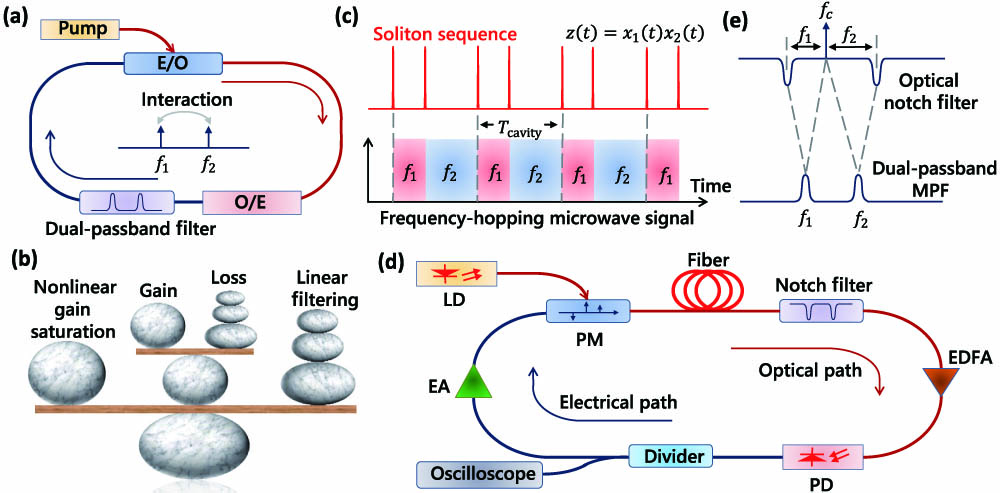
Figure 1.Schematic diagram and operating principle of the spontaneous frequency-hopping soliton OEO. (a) Schematic diagram. A dual-passband filter is used to select two groups of interacting cavity modes. Spontaneous frequency hopping is related to the formation of dissipative microwave photonic solitons due to the interaction between the two groups of modes. (b) Principle of the dissipative microwave photonic solitons. (c) Illustration of the dissipative microwave photonic solitons and the corresponding frequency-hopping microwave signal. The dissipative microwave photonic solitons are the product of wave packets of the two groups of interacting oscillation modes. The solitons maintain their shape due to the double balance between nonlinear gain saturation and linear filtering as well as cavity loss and gain, creating frequency-hopping microwave signals. Whenever a soliton occurs, frequency hopping occurs. (d) Experimental setup. A dual-passband MPF is implemented based on PM-IM conversion using a PM and a dual-passband optical notch filter. (e) Principle of the MPF. The shape of the MPF in the microwave domain is the reverse shape of the optical notch filter in the optical domain, where
According to Eq. (1), we can describe the interaction between the two groups of oscillation modes as follows:
As can be seen from Eq. (3), one result of the interaction between the two groups of modes is the cross-gain saturation effect, where the effective gain of one mode is related to the other one.
In a steady-state operation, the oscillating signal repeats itself after each cavity round trip; thus, we have
In a steady-state operation, the sum of the wave packets of the two groups of modes is also a constant value
As a result, the product of the wave packets of the two groups of interacting modes
The value of
Since Eq. (9) is a delay differential equation, a straightforward analytical solution, i.e., the analytical expression of the solitary wave, is challenging due to the complexity and time-dependence of Eq. (9). Nevertheless, we can analyze and simulate the characteristics of
It should be noted that the gain for a traditional noninteracting oscillation in the OEO decreases with an increase in the signal amplitude, so the interaction between the two groups of modes is essential to achieve the desired gain saturation effect and the dissipative microwave photonic solitons. In addition, the master equation [Eq. (9)] and the physical mechanism of the dissipative microwave photonic solitons are quite different from that of optical solitons. In the reported dissipative microwave photonic solitons, the master equation is the DDE, and soliton pulse shaping (compression and broadening) occurs due to nonlinear gain saturation and linear filtering effects. In optical solitons, the master equation is generally the nonlinear Schrödinger equation or the Landau–Ginsburg equation, and pulse shaping occurs due to nonlinear and dispersion/diffraction effects. Thus, we must clarify that the dissipative microwave photonic solitons can be considered as a new type of dissipative solitons with unique properties, rather than an extension of optical solitons. The natural extension of optical solitons should be an OEO that generates short microwave or optical pulses, where soliton pulse shaping occurs due to nonlinearity and dispersion/diffraction in the optoelectronic cavity. The key advantage of our approach is that it extends the suitability and potential applications of solitons, paving the way for a new class of soliton microwave photonic systems for the generation, processing, and control of microwave signals. Moreover, our frequency-hopping soliton OEO is capable of generating frequency-hopping microwave signals with large bandwidth, fast frequency-hopping speed, and high stability, which are highly desired in various practical application scenarios such as communication, radar, and electronic warfare systems. For example, the frequency-hopping soliton OEO can be used to enlarge the network capacity and improve the anti-interference ability in communication systems. In radar systems, the large time–bandwidth product of the frequency-hopping soliton OEO can bring advantages of increased detection range and improved range resolution.
The dual-passband filter in the soliton OEO cavity can be implemented using different methods. For example, a properly designed electrical filter [42] can be used to select the two groups of interacting oscillation modes. The limitation of an electrical filter is that the center frequencies of the two passbands are typically fixed during fabrication. In order to achieve frequency tunability, an equivalent dual-passband microwave photonic filter (MPF) can be used for mode selection. The details of the soliton OEO with an MPF are shown in Fig. 1(d). The optical part of the soliton OEO consists of a laser diode (LD), a phase modulator (PM), an optical fiber, a dual-passband optical notch filter, an erbium-doped fiber amplifier, and a PD. The electrical part consists of an electrical power divider and an electrical amplifier. The equivalent dual-passband MPF is implemented by combining the PM and the dual-passband optical notch filter to achieve phase modulation to intensity modulation (PM-IM) conversion [43,44]. Filtering in the microwave domain is achieved by equivalent filtering effect incurred by the dual-passband optical filter. As shown in Fig. 1(e), the shape of passbands of the MPF in the microwave domain is the reverse shape of the optical notch filter in the optical domain; thus, the bandwidth of the MPF is the same as that of the optical notch filter. The center frequencies (
3. RESULTS
A. Frequency Hopping in a Dual-Passband MPF-Based Soliton OEO
Experiments are carried out based on the schematic diagram in Fig. 1(d) to verify our theory. The spontaneous frequency-hopping soliton OEO is implemented using commercially available optical and electronic devices. The LD (NKT Koheras Adjustik E15) has an output power of 18 dBm at 1550 nm. The bandwidth of the PM (EOSPACE) is 40 GHz. The optical fiber has a length of 4.5 km. It is a low dispersion fiber that consists of a single-mode fiber and a dispersion-compensating fiber with opposite dispersion. The residual dispersion of the optical fiber is only about 0.848 ps/nm, and the impact of the fiber chromatic dispersion effect can be neglected. The PD is a 15-GHz light wave converter (HP 11982A) with a conversion gain of 300 V/W. The operation of the OEO is monitored using a digital phosphor oscilloscope (Tektronix DSA73304D).
A fiber Fabry–Perot interferometer (FFP-I, Micron Optics) with a bandwidth of 20 MHz is used as the dual-passband optical notch filter. The spontaneous frequency-hopping and dissipative microwave photonic solitons are generated in the OEO loop when two groups of interacting oscillation modes are selected and the double balance between the nonlinear gain saturation and linear filtering as well as the cavity loss and loss is achieved. Figure 2(a) shows the soliton sequence obtained in the experiment. It is acquired by extracting the amplitudes of the two groups of interacting oscillation modes from the temporal waveform and multiplying them. The amplitudes of each group of modes are extracted by separating each of their waveforms into pieces and taking the maximum of each piece. As can be seen from Fig. 2(a), the soliton sequence is periodic, and there are two soliton pulses per period. The soliton period is equal to the cavity round-trip time of the OEO, which is about 22.22 μs in this case. The soliton pulse width is about 43 ns; it is related to the cavity gain and the bandwidth of the MPF. The instantaneous frequency-time diagram, temporal waveform, and spectrum of the spontaneous frequency-hopping microwave signal are shown in Figs. 2(b), 2(c), and 2(e), respectively. The instantaneous frequency-time diagram is obtained by calculating the short-time Fourier transform of the temporal waveform. As shown in Figs. 2(a) and 2(b), frequency hopping occurs when a dissipative microwave photonic soliton is formed, which is consistent with our theory. The temporal waveform indicates that the two groups of frequency-hopping modes have slightly different amplitudes. The details of the temporal waveform when frequency hopping occurs are depicted in Fig. 2(d), indicating that the frequency-hopping speed reaches tens of nanoseconds, which is similar to the soliton pulse width since the soliton is a product of the amplitudes of the two frequency-hopping modes. As can be seen from Fig. 2(e), two groups of modes are activated in the OEO cavity, which is consistent with our theory. We also used a vector network analyzer (R&S ZVA40) to measure the frequency response of the dual-passband MPF; the measurement result is shown in Fig. 2(f). The two frequencies of the frequency-hopping microwave signal are identical to those of the two groups of interacting oscillation modes selected by the dual-passband MPF, which is also consistent with our theory. Moreover, the gains of the two groups of frequency-hopping modes are similar, ensuring the interaction between the modes since they have the same potential for being oscillated in the OEO cavity. The dissipative microwave photonic solitons in the microwave photonic cavity enable the generation of spontaneous frequency-hopping microwave signals, revealing a novel operating mode of the microwave photonic resonator.
![]()
Figure 2.Soliton sequence and spontaneous frequency-hopping microwave signal for a 20-MHz MPF. (a) Soliton sequence. The dissipative microwave photonic solitons are periodic; there are two soliton pulses per cavity round-trip time. The two soliton pulses are marked as s1 and s2 to distinguish them. The magnified view shows the details of the generated solitons with a pulse width of 43 ns. (b) Calculated instantaneous frequency-time diagram of the spontaneous frequency-hopping microwave signal. Frequency hopping occurs when a soliton is formed. (c) Temporal waveform of the spontaneous frequency-hopping microwave signal. The two groups of modes have slightly different amplitudes. (d) Details of the temporal waveform when frequency hopping occurs. The cavity modes are switched from one to the other within tens of nanoseconds. The frequency-hopping speed is similar to the soliton pulse width. (e) Spectrum of the spontaneous frequency-hopping microwave signal. (f) Measured frequency response of the 20-MHz MPF.
As Eq. (9) indicates, the pulse width of the solitons and the frequency-hopping speed are related to the bandwidth of the MPF and cavity gain of the OEO loop. Although a straightforward analytical solution of Eq. (9) is challenging, the pulse width can still be evaluated by altering the experimental parameters and performing a numerical simulation. Figures 3(a)–3(c) show the soliton sequence and instantaneous frequency-time diagram of the frequency-hopping microwave signal for an MPF with a bandwidth of 50 MHz. An optical notch filter with a bandwidth of 50 MHz is used to construct the MPF. A shorter soliton pulse width of 18 ns is achieved due to the reduction in the linear filtering effect. We also simulated the formation of the solitons and frequency-hopping microwave signals in the OEO cavity for a 50-MHz filter, and some of the simulation results are shown in Fig. 4. In the simulation, the soliton OEO is started from random noise and a stable oscillation is obtained by the coherent superposition of the cavity modes as they travel repeatedly in the OEO cavity. We show the simulated soliton sequence and instantaneous frequency-time diagram of the spontaneous frequency-hopping microwave signal in Figs. 4(a) and 4(b); they agree well with the experimental results in Figs. 3(a) and 3(c). The simulated temporal waveform of the spontaneous frequency-hopping microwave signal is shown in Fig. 4(c). The simulated amplitude of the two groups of frequency-hopping modes is the same because the gain of the two modes is the same in the simulation. Figure 4(d) shows the details of the temporal waveform when frequency hopping occurs, which is consistent with the experimental results.
![]()
Figure 3.Tuning of the spontaneous frequency-hopping soliton OEO. The frequency-hopping speed, frequency, period, and frequency-hopping number can be tuned. (a) Generated soliton sequence for a 50-MHz MPF. (b) Details of the soliton sequence. Blue dashed line: simulation result. Red line: experimental result. The pulse width is about 18 ns, which is shorter than that of the 20-MHz MPF because of the reduction in the linear filtering effect. (c) Calculated instantaneous frequency-time diagram of the spontaneous frequency-hopping microwave signal. (d) Soliton pulse width for different gains and filter bandwidths.
![]()
Figure 4.Simulation results when a 50-MHz dual-passband filter is used in the frequency-hopping soliton OEO. (a) Soliton sequence. (b) Instantaneous frequency-time diagram of the spontaneous frequency-hopping microwave signal. (c) Temporal waveform. (d) Details of the temporal waveform when frequency hopping occurs.
Since the 3-dB bandwidth of the optical notch filter is fixed once fabricated, we implemented several simulations with different filter bandwidths to further show the tunability of the proposed dissipative solitons. We also simulated the soliton pulse width for different gains; the results are shown in Fig. 3(d). A shorter soliton pulse width and a faster frequency-hopping speed are achieved for a wider filter bandwidth or larger gain. Thus, the soliton pulse width and the frequency-hopping speed can be tailored. The repetition rate and the frequencies of the frequency-hopping microwave signal can also be tuned by simply changing the cavity round-trip time and the center frequencies of the MPF of the OEO, respectively. Moreover, the frequency-hopping number per round trip can be changed even when the cavity round-trip time and the passbands of the MPF are fixed. The reason is that although the double balance between the nonlinear gain saturation and linear filtering as well as the cavity loss and gain enables the stable operation of the spontaneous frequency-hopping soliton OEO, the frequency-hopping number is not predetermined by this operation. According to our numerical simulations, the frequency-hopping number is related to the initial condition of the OEO cavity when the oscillation starts from noise. Nevertheless, the spontaneous frequency-hopping soliton OEO is stable once the oscillation is established. It should also be noted that the remaining key parameters of the spontaneous frequency-hopping soliton OEO, such as the soliton pulse width, frequency-hopping speed, repetition rate, and frequencies, are predetermined by the system parameters rather than by the initial conditions, which is highly desirable for practical applications. Figures 3(e) and 3(f) show the experimental results of the instantaneous frequency-time diagram of the spontaneous frequency-hopping microwave signal with different frequencies, repetition rates, and frequency-hopping numbers per round trip. A high repetition rate of 0.45 MHz is achieved in the experiment when a spool of 450-m fiber is used. The repetition rate can be further increased by reducing the loop length of the OEO, e.g., using photonic integrated circuits [45]. Thus, a high repetition rate of tens of gigahertz can be expected, enabling the generation of wideband frequency-hopping microwave signals with ultra-fast frequency-hopping speed and solving the bottleneck of current frequency-hopping RF technology.
B. Universality of the Spontaneous Frequency-Hopping Soliton OEO
According to our theory, spontaneous frequency hopping is a universal phenomenon in a soliton OEO, as long as two groups of interacting oscillation modes are selected. We have observed the generation of spontaneous frequency-hopping microwave signals and soliton sequences for different OEO configurations. For instance, in addition to the dual-passband MPF-based setup shown in Fig. 1(d), frequency-hopping and soliton sequences have also been observed in a wideband filter-based OEO, as shown in Fig. 5. As can be seen from the schematic diagram in Fig. 5(a), an optical bandpass filter is used in this case. The joint operation of the PM and the optical bandpass filter corresponds to a broadband MPF. Figure 5(b) shows the measured open-loop response (S21) of the broadband MPF-based OEO. An appropriate control of the cavity ensures that only the gain of two groups of cavity modes is above the threshold; thus, the two groups of modes can interact, enabling the formation of dissipative microwave photonic solitons and spontaneous frequency-hopping microwave signals. Figures 5(c)–5(e) show the measured temporal waveform, soliton sequence, and instantaneous frequency-time diagram of the spontaneous frequency-hopping microwave signal, demonstrating the universality of the spontaneous frequency-hopping phenomenon in soliton OEOs. It should be noted that other types of solitons or mode-locked pulses have also been previously reported in OEOs [46,47] and microwave systems [11]. Although each of them has distinctive features, they can be classified as natural extensions of traditional optical solitons for the generation of short optical or electrical pulses. The solitons in this paper can be considered as a new type of solitons with unique features, rather than a natural extension of optical solitons. Thus, we believe that our work greatly extends the suitability and potential applications of solitons, and it will be of significant interest to a general readership of scientists working in microwave photonics, solitons, and related areas.
![]()
Figure 5.Frequency-hopping and soliton sequence in a different OEO structure, demonstrating the universality of the spontaneous frequency-hopping phenomenon in soliton OEOs. (a) Schematic diagram. An optical bandpass filter instead of a dual-passband filter is used in the optical path. The joint use of the PM and optical bandpass filter corresponds to a broadband MPF. (b) Measured open-loop response of the OEO. Only the gain of the two groups of interacting modes is above threshold; thus, two groups of interacting modes can be selected by the broadband MPF. (c) Temporal waveform of the spontaneous frequency-hopping microwave signal. (d) Corresponding soliton sequence. (e) Instantaneous frequency-time diagram of the frequency-hopping microwave signal.
C. Stability of the Soliton OEO
The phase noise performance is a crucial figure of merit of a microwave source and reflects the short-term stability of the generated microwave signal. Low phase noise is highly desirable in real-world applications, such as radar, wireless communication, and cognitive radio networks. Figure 6 shows the comparison of the measured phase noise performance of the soliton OEO and a commercial electrical frequency-hopping source (Tektronix AWG70001). The phase noise performance of the soliton OEO can be enhanced by using a spool of long optical fiber or a narrowband filter. A low phase noise of
![]()
Figure 6.Comparison of the phase noise performance of the soliton OEO and an electrical frequency-hopping source. The soliton OEO provides lower phase noise by using a long optical fiber and a narrowband filter. The phase noise of the soliton OEO is as low as
We also measured the output waveform during 200 ms using an oscilloscope to evaluate the long-term stability of the reported soliton OEO. Due to the limited record length (15 Mpts) of the oscilloscope, the time duration can only be extended when the sampling rate is low since their product is equal to the record length. Therefore, sub-Nyquist sampling with a sampling rate of 62.5 MS/s is used. The measured temporal waveform is shown in Fig. 7; the
![]()
Figure 7.Temporal waveform of the frequency-hopping soliton OEO during 9000 round trips. Sub-Nyquist sampling with a sampling rate of 62.5 MS/s is used. The total time duration is 200 ms. The frequency-hopping signal is stable after thousands of round trips.
D. Comparison of the Soliton OEO and Related Works
Table 1 shows a comparison of the generation approaches and characteristics of different solitons. As can be seen, the generation of different solitons with attractive features has been reported in various physical platforms ranging from optical fibers, microresonators, lasers, neuronal networks, electrical oscillators, plasmas, cold atoms, to optoelectronic oscillators. Although the physical platforms and signal types may be different, the key soliton pulse shaping mechanism is similar for these solitons, i.e., based on the pulse shaping of nonlinearity and dispersion/diffraction. In this work, we reported a novel soliton OEO with pulse shaping related to nonlinearity and filtering. This novel pulse shaping mechanism leads to the unique properties of the proposed dissipative solitons and paves the way for a new class of soliton microwave photonic systems for the generation, processing, and control of microwave and RF signals.
Comparison of Different Solitons in Selected Physical Systems
| Source | Physical Platform | Nonlinear and Linear Effects in Soliton Pulse Shaping | Signal Type |
|---|---|---|---|
| Ref. [ | Optical fibers | Nonlinearity and dispersion | Optical pulses |
| Ref. [ | Optical microresonators | Nonlinearity and dispersion | Optical pulses |
| Ref. [ | Mode-locked lasers | Nonlinearity and dispersion | Optical pulses |
| Ref. [ | Semiconductor lasers | Nonlinearity and diffraction | Self-localized optical beams |
| Ref. [ | Neuronal networks | Nonlinearity and dispersion | Nerve pulses |
| Ref. [ | Electrical oscillators | Nonlinearity and dispersion | Electrical pulses |
| Ref. [ | Plasmas | Nonlinearity and dispersion | Electronic-acoustic pulses |
| Ref. [ | Cold atoms | Nonlinearity and diffraction | Self-localized atomic densities |
| Ref. [ | Optoelectronic oscillators | Nonlinearity and dispersion | Optical and electrical pulses |
| This work | Optoelectronic oscillators | Nonlinearity and filtering | Frequency-hopping microwave signals |
The reported dissipative microwave photonic solitons give rise to frequency-hopping microwave signals, so it is interesting to compare it with other frequency-hopping microwave signal generation approaches in terms of key parameters such as bandwidth, frequency-hopping speed, and stability. Frequency-hopping microwave signals can be generated using conventional electrical methods, which is a relatively mature technique. However, the bandwidth and frequency-hopping speed are generally limited to few gigahertz and kilohertz, respectively, due to the electronic bottleneck. In recent years, several microwave photonic methods have been proposed and demonstrated to produce frequency-hopping microwave signals, for example, based on optical injection [50], bias control of an electro-optic modulator [51], and frequency-to-time mapping [52]. Frequency-hopping microwave signals with a large bandwidth and fast frequency-hopping speed have been successfully obtained. Nevertheless, a high-speed electrical signal source is required or the phase noise performance is poor. Based on our soliton OEO, frequency-hopping microwave signals with large bandwidth, fast frequency-hopping speed, and unprecedented low phase noise performance can be obtained without the requirement of high-speed electrical signal sources; thus, the proposed approach can solve the bottleneck of current RF technology and be used in various practical applications. It should also be noted that in order to obtain the desired dissipative microwave photonic solitons, precise control of the nonlinear and linear effects is required to make sure that the two groups of modes in the OEO cavity have the same potential for being oscillated; otherwise the soliton OEO will degenerate into a traditional single-frequency OEO. In addition, the gain in the OEO cavity should also be controlled properly. Other unwanted dynamic states will occur if the gain is too large [37].
4. CONCLUSIONS
In conclusion, we reported a novel operating state of OEOs related to the formation of dissipative microwave photonic solitons. The product of the wave packets of two groups of interacting oscillation modes in the OEO cavity is a dissipative soliton that maintains its shape due to the delicate double balance between nonlinear gain saturation and linear filtering as well as cavity loss and gain in the microwave photonic cavity. Spontaneous frequency hopping can be achieved from the soliton OEO cavity due to pulse shaping during the formation of the dissipative microwave photonic solitons. We have observed the generation of soliton sequences and spontaneous frequency-hopping microwave signals in different OEO configurations such as dual-passband MPF-based OEO and wideband filter-based OEO, demonstrating the universality of this phenomenon. Reconfigurable soliton sequences and frequency-hopping microwave signals with soliton pulse width and frequency-hopping speed up to tens of nanoseconds, frequency as high as tens of gigahertz, and phase noise as low as
References
[1] A. M. Wazwaz. Partial Differential Equations and Solitary Waves Theory(2009).
[2] A. C. Scott, F. Y. F. Chu, D. W. McLaughlin. The soliton: a new concept in applied science. Proc. IEEE, 61, 1443-1483(1973).
[3] L. F. Mollenauer, R. H. Stolen, J. P. Gordon. Experimental observation of picosecond pulse narrowing and solitons in optical fibers. Phys. Rev. Lett., 45, 1095-1098(1980).
[4] B. Shen, L. Chang, J. Liu, H. Wang, Q.-F. Yang, C. Xiang, R. N. Wang, J. He, T. Liu, W. Xie, J. Guo, D. Kinghorn, L. Wu, Q.-X. Ji, T. J. Kippenberg, K. Vahala, J. E. Bowers. Integrated turnkey soliton microcombs. Nature, 582, 365-369(2020).
[5] T. J. Kippenberg, A. L. Gaeta, M. Lipson, M. L. Gorodetsky. Dissipative Kerr solitons in optical microresonators. Science, 361, eaan8083(2018).
[6] T. Herr, V. Brasch, J. D. Jost, C. Y. Wang, N. M. Kondratiev, M. L. Gorodetsky, T. J. Kippenberg. Temporal solitons in optical microresonators. Nat. Photonics, 8, 145-152(2014).
[7] P. Grelu, N. Akhmediev. Dissipative solitons for mode-locked lasers. Nat. Photonics, 6, 84-92(2012).
[8] X. Liu. Numerical and experimental investigation of dissipative solitons in passively mode-locked fiber lasers with large net-normal-dispersion and high nonlinearity. Opt. Express, 17, 22401-22416(2009).
[9] T. Ackemann, W. J. Firth, G. L. Oppo. Fundamentals and applications of spatial dissipative solitons in photonic devices. Adv. Atom. Mol. Opt. Phys., 57, 323-421(2009).
[10] N. Akhmediev, A. Ankiewicz. Dissipative Solitons: From Optics to Biology and Medicine(2008).
[11] D. S. Ricketts, X. Li, D. Ham. Electrical soliton oscillator. IEEE Trans. Microwave Theory Tech., 54, 373-382(2006).
[12] D. S. Ricketts, E. Shi, X. Li, N. Sun, O. O. Yildirim, D. Ham. Electrical solitons for microwave systems: harmonizing nonlinearity and dispersion with nonlinear transmission line. IEEE Microw. Mag., 20, 123-134(2019).
[13] S. Sultana, R. Schlickeiser, I. S. Elkamash, I. Kourakis. Dissipative high-frequency envelope soliton modes in nonthermal plasmas. Phys. Rev. E, 98, 033207(2018).
[14] M. Selim Habib, C. Markos, O. Bang, M. Bache. Soliton-plasma nonlinear dynamics in mid-IR gas-filled hollow-core fibers. Opt. Lett., 42, 2232-2235(2017).
[15] P. K. Shukla, A. A. Mamun. Solitons shocks and vortices in dusty plasmas. New J. Phys., 5, 17(2003).
[16] B. Doyon, T. Yoshimura, J.-S. Caux. Soliton gases and generalized hydrodynamics. Phys. Rev. Lett., 120, 045301(2018).
[17] E. A. Kuznetsov, A. M. Rubenchik, V. E. Zakharov. Soliton stability in plasmas and hydrodynamics. Phys. Rep., 142, 103-165(1986).
[18] S. A. Arsen’yev. Mathematical modeling of tornadoes and squall line storms. Geosci. Front, 2, 215-221(2011).
[19] E. Tesio, G. R. M. Robb, T. Ackemann, W. J. Firth, G. L. Oppo. Dissipative solitons in the coupled dynamics of light and cold atoms. Opt. Express, 21, 26144-26149(2013).
[20] N. S. Manton. Solitons as elementary particles: a paradigm scrutinized. Nonlinearity, 21, T221(2008).
[21] G. P. Pronko. Soliton in gravitating gas: Hoag’s object. Theor. Math Phys., 146, 85-94(2006).
[22] S. V. Antipov, M. V. Nezlin, E. N. Snezhkin, A. S. Trubnikov. Rossby autosoliton and stationary model of the Jovian great red spot. Nature, 323, 238-240(1986).
[23] A. R. Bishop, J. A. Krumhansl, S. E. Trullinger. Solitons in condensed matter: a paradigm. Physica D, 1, 1-44(1980).
[24] D. Marpaung, J. Yao, J. Capmany. Integrated microwave photonics. Nat. Photonics, 13, 80-90(2019).
[25] J. Yao. Microwave photonics. J. Lightwave Technol., 27, 314-335(2009).
[26] J. Capmany, D. Novak. Microwave photonics combines two worlds. Nat. Photonics, 1, 319-330(2007).
[27] A. J. Seeds, K. J. Williams. Microwave photonics. J. Lightwave Technol., 24, 4628-4641(2006).
[28] X. S. Yao, L. Maleki. Optoelectronic microwave oscillator. J. Opt. Soc. Am. B, 13, 1725-1735(1996).
[29] L. Maleki. The optoelectronic oscillator. Nat. Photonics, 5, 728-730(2011).
[30] T. Hao, Y. Liu, J. Tang, Q. Cen, W. Li, N. Zhu, Y. Dai, J. Capmany, J. Yao, M. Li. Recent advances in optoelectronic oscillators. Adv. Photonics, 2, 044001(2020).
[31] D. Eliyahu, D. Seidel, L. Maleki. Phase noise of a high performance OEO and an ultra-low noise floor cross-correlation microwave photonic homodyne system. IEEE International Frequency Control Symposium, 811-814(2008).
[32] T. Hao, J. Tang, D. Domenech, W. Li, N. Zhu, J. Capmany, M. Li. Toward monolithic integration of OEOs: from systems to chips. J. Lightwave Technol., 36, 4565-4582(2018).
[33] W. Li, J. Yao. A wideband frequency tunable optoelectronic oscillator incorporating a tunable microwave photonic filter based on phase-modulation to intensity-modulation conversion using a phase-shifted fiber Bragg grating. IEEE Trans. Microwave Theory Tech., 60, 1735-1742(2012).
[34] Z. Tang, S. Pan, D. Zhu, R. Guo, Y. Zhao, M. Pan, D. Ben, J. Yao. Tunable optoelectronic oscillator based on a polarization modulator and a chirped FBG. IEEE Photonics Technol. Lett., 24, 1487-1489(2012).
[35] H. Peng, Y. Xu, X. Peng, X. Zhu, R. Guo, F. Chen, H. Du, Y. Chen, C. Zhang, L. Zhu, W. Hu, Z. Chen. Wideband tunable optoelectronic oscillator based on the deamplification of stimulated Brillouin scattering. Opt. Express, 25, 10287-10305(2017).
[36] T. Hao, Q. Cen, Y. Dai, J. Tang, W. Li, J. Yao, N. Zhu, M. Li. Breaking the limitation of mode building time in an optoelectronic oscillator. Nat. Commun., 9, 1839(2018).
[37] Y. K. Chembo, D. Brunner, M. Jacquot, L. Larger. Optoelectronic oscillators with time-delayed feedback. Rev. Mod. Phys., 91, 035006(2019).
[38] Y. K. Chembo, L. Larger, P. Colet. Nonlinear dynamics and spectral stability of optoelectronic microwave oscillators. IEEE J. Quantum Electron., 44, 858-866(2008).
[39] M. Peil, M. Jacquot, Y. K. Chembo, L. Larger, T. Erneux. Routes to chaos and multiple time scale dynamics in broadband bandpass nonlinear delay electro-optic oscillators. Phys. Rev. E, 79, 026208(2009).
[40] T. Hao, Q. Cen, S. Guan, W. Li, Y. Dai, N. Zhu, M. Li. Optoelectronic parametric oscillator. Light Sci. Appl., 9, 102(2020).
[41] Z. Ge, T. Hao, J. Capmany, W. Li, N. Zhu, M. Li. Broadband random optoelectronic oscillator. Nat. Commun., 11, 5724(2020).
[42] G. Macchiarella, S. Tamiazzo. Design techniques for dual-passband filters. IEEE Trans. Microwave Theory Tech., 53, 3265-3271(2005).
[43] X. S. Yao. Phase to amplitude modulation conversion using Brillouin selective sideband amplification. IEEE Photonics Technol. Lett., 10, 264-266(1998).
[44] W. Li, M. Li, J. Yao. A narrow-passband and frequency-tunable micro-wave photonic filter based on phase-modulation to intensity-modulation conversion using a phase-shifted fiber Bragg grating. IEEE Trans. Microwave Theory Tech., 60, 1287-1296(2012).
[45] J. Tang, T. Hao, W. Li, D. Domenech, R. Banos, P. Muñoz, N. Zhu, J. Capmany, M. Li. Integrated optoelectronic oscillator. Opt. Express, 26, 12257-12265(2018).
[46] Y. K. Chembo, A. Hmima, P. Lacourt, L. Larger, J. M. Dudley. Generation of ultralow jitter optical pulses using optoelectronic oscillators with time-lens soliton-assisted compression. J. Lightwave Technol., 27, 5160-5167(2009).
[47] E. C. Levy, M. Horowitz. Single-cycle radio-frequency pulse generation by an optoelectronic oscillator. Opt. Express, 19, 17599-17608(2011).
[48] P. Yao, L. Xu, Z. Sun. Design of low-noise X-band frequency source based on DDS-PLL. IEEE 2nd International Conference on Circuits and Systems (ICCS), 11-14(2020).
[49] Y. Zhang, A. Zhang, C. He, C. Hou, J. Xu. Design of a fast-sweeping C-X band frequency source based on DDS and frequency multiplying chain. International Conference on Microwave and Millimeter Wave Technology (ICMMT), 1-3(2021).
[50] P. Zhou, F. Zhang, X. Ye, Q. Guo, S. Pan. Flexible frequency-hopping microwave generation by dynamic control of optically injected semiconductor laser. IEEE Photonics J., 8, 5501909(2016).
[51] Y. Chen. High-speed and wideband frequency-hopping microwave signal generation via switching the bias point of an optical modulator. IEEE Photonics J., 10, 5500407(2018).
[52] A. Rashidinejad, A. M. Weiner. Photonic radio-frequency arbitrary waveform generation with maximal time-bandwidth product capability. J. Lightwave Technol., 32, 3383-3393(2014).


Set citation alerts for the article
Please enter your email address

© Copyright 2018-2021 | Chinese Laser Press. All Rights Reserved 沪ICP备15018463号-20