
Cheng-Zhe Chai, Zhen Shen, Yan-Lei Zhang, Hao-Qi Zhao, Guang-Can Guo, Chang-Ling Zou, Chun-Hua Dong, "Single-sideband microwave-to-optical conversion in high-Q ferrimagnetic microspheres," Photonics Res. 10, 820 (2022)
- Photonics Research
- Vol. 10, Issue 3, 820 (2022)
Abstract
1. INTRODUCTION
Electromagnetic waves at microwave and optical frequencies play important roles in information processing and communications systems. However, the quantum information technology based on the most promising superconducting qubits is operated at cryogenic temperature with microwave photons, which cannot achieve long-distance communications between qubits. Unlike microwave photons, the optical photon can transmit via low loss optical fibers, making them suitable for long-distance communications. Thus, frequency conversion between a microwave photon and an optical photon has attracted great interest [1–6]. Besides, the energy of a single microwave photon is too low to be efficiently detected with a high signal-to-noise ratio (SNR). In contrast, converting the microwave photons to optical photons can be detected directly with single-photon detectors. Therefore, it can greatly promote the detection based on the microwave, help to improve the resolution of radar, and maybe realize the quantum-enhanced radar system [7]. Recently, such a microwave-to-optical transducer [6] has been demonstrated in optomechanics, electro-optic interaction, atoms, and ions [8–17]. Among these approaches, optomagnonics based on a magnon provides an alternative and attractive approach to the coherent microwave-to-optical conversion because of its great frequency tuning range and long coherence time [18–24]. Besides, due to the nonlinearity of the system, high-order sidebands can be generated in optomagnonics [25].
Currently, frequency conversion has been demonstrated in such an optomagnonic system [26–30], where the high-Q yttrium iron garnet (YIG) whispering gallery mode (WGM) microcavity was used to enhance the interaction between magnons and photons, and nonreciprocity of the magnetic Brillouin light scattering (BLS) has been observed [28,31]. However, similar to the Brillouin optomechanical system [32,33], the triple-resonance condition (the phase matching between pump, signal, and magnetic modes) is required in such systems, which may limit the flexibility in choosing the working frequencies and tunability of the frequencies. Therefore, using the great tunability of the magnon and also the two-mode magnon–photon coupling mechanism would allow us to achieve the transducer that mitigates the limitations mentioned above.
In this paper, a tunable frequency conversion between microwave and photons is realized by the dynamical Faraday effect in a YIG microsphere. The magnetic Stokes and anti-Stokes scattering induced by the dispersive interaction between the magnon mode and the optical mode can be observed. When the frequency of the pump light is resonant with the optical mode, the asymmetry of the two sidebands and even a single sideband (SSB) is observed in our experiment. By changing the direction of the static external magnetic field, we observed both the optical mode resonance frequency shift and the modulated coupling efficiency, corresponding to both phase and intensity modulations. Therefore, we deduced that this asymmetry conversion is derived from the phase and intensity modulations induced by the internal magnetization procession. In our experiment, we demonstrated 16 times asymmetry of the two sidebands and a magnon tuning range of 2.5 GHz, corresponding to the tunable frequency conversion with the same range. We believe, to the best of our knowledge, that our results serve as a novel method for the implementation of SSB microwave-to-optical conversion devices.
Sign up for Photonics Research TOC. Get the latest issue of Photonics Research delivered right to you!Sign up now
2. EXPERIMENTAL SETUP AND RESULTS
The principle of the frequency conversion in the YIG microsphere is illustrated in Fig. 1(a). The input light couples to the YIG microcavity and excites the WGMs through the high-index prism. The WGMs in the microcavity will have a spin along the z direction due to the spin-orbit coupling of light [34–36]. According to our previous work, the spin will be modulated by the magnetization along the z direction due to the Faraday effect, thus shifting the resonant frequency of the WGMs [34]. When applying a magnetic field parallel to the resonator equator, the microwave excites the magnon mode in the microcavity by an antenna and causes the procession of the magnetization in the microcavity. Therefore, as shown in Fig. 1(c), the resonant frequency of the optical mode in the microcavity will be modulated by the magnetization procession. When an optical pump drives at the optical mode, its amplitude will be modulated and lead to two sidebands at the output as an oscillator system, and the Hamiltonian of the system can be written as
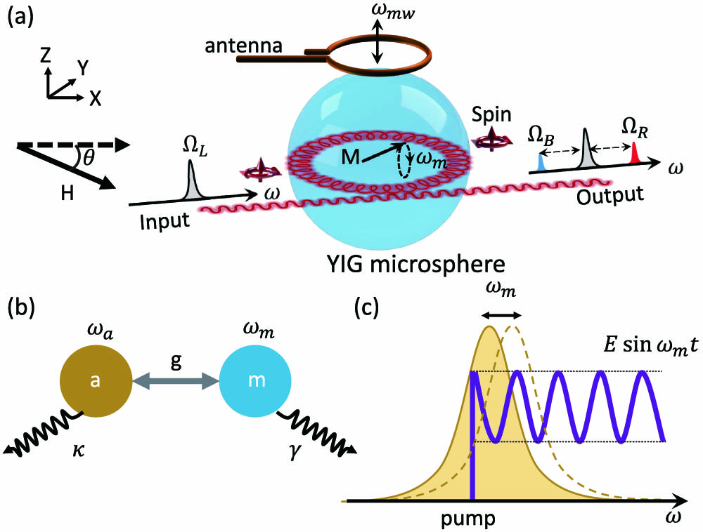
Figure 1.(a) Schematic of the microwave-to-optical frequency conversion in a YIG microsphere. The bias magnetic field is parallel to the optical path, while the input light excites the WGMs and has an optical spin perpendicular to the propagating direction due to the spin-orbit coupling. The intracavity field could be modulated by the dynamic magnetic field via the Faraday effect, and generate two sidebands at the output port. (b) Frequency conversion via the coupling between photon (
Figure 2(a) is the schematic of our experimental setup. A tunable diode laser is separated into two laser beams by an optical fiber splitter. One beam excites the WGMs by the rutile prism, and would generate two sidebands due to the interaction between the magnons and photons. Another laser beam is shifted with a frequency of
![]()
Figure 2.(a) Schematic of the experimental setup. A tunable laser is separated into two beams by an optical fiber splitter. One beam excites the WGMs by prism coupling, which would generate two sidebands at the output, and then combines another beam as the local oscillator (LO) is shifted by an acousto-optical modulator (AOM). PBS, polarization beam splitter; HWP, half-wave plate; FPC, fiber polarization controller; PD, photon detector; ESA, electric spectrum analyzer. Inset: spectral position of the pump laser, the sidebands, and the probe laser as the local oscillator. (b) The detected beat signal when the optical pump is at red and blue detunings, respectively. The
The pump laser with a frequency of
When the pump laser is scanning through the cavity modes, the typical transmission is shown in Fig. 3(a). The dotted line is a Lorentz fitting, corresponding to the loaded
![]()
Figure 3.(a), (b) Optical pump transmission and the generated optical signal as a function of the pump laser frequency. The experimental results agree well with the numerical calculations. (c) Transmission as a function of the input light frequency with different bias magnetic field direction. (d) The frequency shift and linewidth of the optical mode as a function of the bias magnetic field direction from (c). (e)
Surprisingly, when the pump laser is resonant with the optical mode, the two sidebands signals are asymmetric in Fig. 3(b), in contrast to the symmetric sidebands reported in the dispersively coupled optomechanical systems [38,39]. To investigate the physical mechanism for this novel SSB phenomenon, Fig. 3(c) shows the optical transmission when changing the magnetic field direction, corresponding to the magnetic field direction changed with the microwave signal. The angle
To consider the optical mode owning two modulations with the dynamic magnetic field induced by the microwave, one is the frequency modulation
As we know, the external magnetic field can tune the frequency of the magnon, corresponding to the tunable frequency conversion. Figure 4 shows the frequency conversion when only tuning the relevant magnon frequency from 3.5 to 6 GHz, a range that is limited by the permanent magnet we used. It shows that our device has a much larger operation bandwidth compared to the previous scheme [26–29]. Taking the insertion losses into consideration, the power conversion efficiency in our experiment is estimated as
![]()
Figure 4.Converted signal as a function of the pump laser frequency detuning with different magnon frequencies by changing the magnetic field.
The conversion efficiency can be improved by introducing a second microcavity to approach the first microcavity, so that the optical mode will split due to strong coupling between two microcavities [10]. The coupling strength is tunable, so the splitting of the optical mode can be selected to match the required magnon frequency to achieve the optical pump and sideband signal resonant with the optical modes. Then the photon number conversion efficiency
3. CONCLUSION
We experimentally demonstrate the SSB frequency conversion between microwave and optical photons in a YIG microcavity. By applying the static magnetic field parallel to the resonator equator, the magnetic Stokes and anti-Stokes scattering occurs in the YIG microsphere, which resembles the phonon–photon interaction in an optomechanical system. Besides, due to the modulation of both the resonance frequency and external coupling intensity of optical modes, the SSB modulation has been demonstrated in our experiment. Our results provide what we believe is a novel method to realize the SSB frequency transducer.
Acknowledgment
Acknowledgment. C.-H. Dong was also supported by the State Key Laboratory of Advanced Optical Communication Systems and Networks, Shanghai Jiao Tong University, China. This work was partially carried out at the USTC Center for Micro and Nanoscale Research and Fabrication.
APPENDIX A
The optical transmissions measured in our experiment are shown in Fig.
![]()
Figure 5.Typical transmission of the YIG microcavity with TE and TM modes via prism coupling.
APPENDIX B
In our research, we also found that the strength of the magnetic field will affect the transmission. As shown in Fig.
![]()
Figure 6.Transmission as a function of the input light frequency with different bias magnetic field strength.
To verify that the single-sideband effect we observed is not caused by an accidental optical mode, we determined that the transmission at the magnetic strength is zero and saturation in a free optical spectral region (FSR), as shown in Fig.
APPENDIX C
In our experiment, there is only one optical mode and one magnon mode that participate in the magneto–optical interaction. As mentioned in the main text, the Hamiltonian of the system is
Under external optical and microwave drive, the Hamiltonian of the system is
Parameters Used in the Numerical Simulations
| Parameter | Symbol | Value |
|---|---|---|
| External coupling rate of the optical mode | ||
| Decay rate of the optical mode | ||
| External coupling rate of the magnon mode | ||
| Decay rate of the magnon mode | ||
| Optical pump power | 0.01 W | |
| Microwave pump power | 1 W | |
| Frequency of the optical mode | ||
| Frequency of the magnon mode | ||
| Modulation constant of | 1 | |
| Coupling strength of the magneto–optical interaction |
The numerical results based on the parameter values above are shown in Fig.
APPENDIX D
In our experiment, we used a Fabry–Perót (FP) cavity with an FSR of 10 GHz to estimate the conversion efficiency of the system. As shown in Fig.
![]()
Figure 7.(a)–(c) Transmission and the generated optical signal as a function of the optical pump laser detuning at various optical modes in one optical FSR. The target optical modes show the great change of transmission when the magnetic field intensity is zero (the bottom line) and
![]()
Figure 8.(a) Sideband signal measured in a Fabry–Perót cavity. (b) Converted optical signal change with microwave power.
References
[1] R. W. Andrews, R. W. Peterson, T. P. Purdy, K. Cicak, R. W. Simmonds, C. A. Regal, K. W. Lehnert. Bidirectional and efficient conversion between microwave and optical light. Nat. Phys., 10, 321-326(2014).
[2] J. Bochmann, A. Vainsencher, D. D. Awschalom, A. N. Cleland. Nanomechanical coupling between microwave and optical photons. Nat. Phys., 9, 712-716(2013).
[3] A. Rueda, F. Sedlmeir, M. C. Collodo, U. Vogl, B. Stiller, G. Schunk, D. V. Strekalov, C. Marquardt, J. M. Fink, O. Painter, G. Leuchs, H. G. L. Schwefel. Efficient microwave to optical photon conversion: an electro-optical realization. Optica, 3, 597-604(2016).
[4] N. J. Lambert, A. Rueda, F. Sedlmeir, H. G. Schwefel. Coherent conversion between microwave and optical photons: an overview of physical implementations. Adv. Quantum Technol., 3, 1900077(2020).
[5] L. Fan, C.-L. Zou, R. Cheng, X. Guo, X. Han, Z. Gong, S. Wang, H. X. Tang. Superconducting cavity electro-optics: a platform for coherent photon conversion between superconducting and photonic circuits. Sci. Adv., 4, eaar4994(2018).
[6] X. Han, W. Fu, C.-L. Zou, L. Jiang, H. X. Tang. Microwave-optical quantum frequency conversion. Optica, 8, 1050-1064(2021).
[7] S. Barzanjeh, S. Guha, C. Weedbrook, D. Vitali, J. H. Shapiro, S. Pirandola. Microwave quantum illumination. Phys. Rev. Lett., 114, 080503(2015).
[8] A. Vainsencher, K. Satzinger, G. Peairs, A. Cleland. Bi-directional conversion between microwave and optical frequencies in a piezoelectric optomechanical device. Appl. Phys. Lett., 109, 033107(2016).
[9] K. C. Balram, M. I. Davanço, J. D. Song, K. Srinivasan. Coherent coupling between radiofrequency, optical and acoustic waves in piezo-optomechanical circuits. Nat. Photonics, 10, 346-352(2016).
[10] M. Soltani, M. Zhang, C. Ryan, G. J. Ribeill, C. Wang, M. Loncar. Efficient quantum microwave-to-optical conversion using electro-optic nanophotonic coupled resonators. Phys. Rev. A, 96, 043808(2017).
[11] A. P. Higginbotham, P. Burns, M. Urmey, R. Peterson, N. Kampel, B. Brubaker, G. Smith, K. Lehnert, C. Regal. Harnessing electro-optic correlations in an efficient mechanical converter. Nat. Phys., 14, 1038-1042(2018).
[12] Y. Xu, A. A. Sayem, L. Fan, C.-L. Zou, S. Wang, R. Cheng, W. Fu, L. Yang, M. Xu, H. X. Tang. Bidirectional interconversion of microwave and light with thin-film lithium niobate. Nat. Commun., 12, 4453(2021).
[13] T. Vogt, C. Gross, J. Han, S. B. Pal, M. Lam, M. Kiffner, W. Li. Efficient microwave-to-optical conversion using Rydberg atoms. Phys. Rev. A, 99, 023832(2019).
[14] B. T. Gard, K. Jacobs, R. McDermott, M. Saffman. Microwave-to-optical frequency conversion using a cesium atom coupled to a superconducting resonator. Phys. Rev. A, 96, 013833(2017).
[15] D. Petrosyan, K. Mølmer, J. Fortágh, M. Saffman. Microwave to optical conversion with atoms on a superconducting chip. New J. Phys., 21, 073033(2019).
[16] S. Welinski, P. J. Woodburn, N. Lauk, R. L. Cone, C. Simon, P. Goldner, C. W. Thiel. Electron spin coherence in optically excited states of rare-earth ions for microwave to optical quantum transducers. Phys. Rev. Lett., 122, 247401(2019).
[17] J. R. Everts, M. C. Berrington, R. L. Ahlefeldt, J. J. Longdell. Microwave to optical photon conversion via fully concentrated rare-earth-ion crystals. Phys. Rev. A, 99, 063830(2019).
[18] A. V. Chumak, V. I. Vasyuchka, A. A. Serga, B. Hillebrands. Magnon spintronics. Nat. Phys., 11, 453-461(2015).
[19] M. Harder, Y. Yang, B. Yao, C. Yu, J. Rao, Y. Gui, R. Stamps, C.-M. Hu. Level attraction due to dissipative magnon-photon coupling. Phys. Rev. Lett., 121, 137203(2018).
[20] Y. Tabuchi, S. Ishino, A. Noguchi, T. Ishikawa, R. Yamazaki, K. Usami, Y. Nakamura. Coherent coupling between a ferromagnetic magnon and a superconducting qubit. Science, 349, 405-408(2015).
[21] D. Lachance-Quirion, S. P. Wolski, Y. Tabuchi, S. Kono, K. Usami, Y. Nakamura. Entanglement-based single-shot detection of a single magnon with a superconducting qubit. Science, 367, 425-428(2020).
[22] D. Lachance-Quirion, Y. Tabuchi, A. Gloppe, K. Usami, Y. Nakamura. Hybrid quantum systems based on magnonics. Appl. Phys. Express, 12, 070101(2019).
[23] S. Viola Kusminskiy, H. X. Tang, F. Marquardt. Coupled spin-light dynamics in cavity optomagnonics. Phys. Rev. A, 94, 033821(2016).
[24] J. Graf, H. Pfeifer, F. Marquardt, S. V. Kusminskiy. Cavity optomagnonics with magnetic textures: coupling a magnetic vortex to light. Phys. Rev. B, 98, 241406(2018).
[25] Z.-X. Liu, B. Wang, H. Xiong, Y. Wu. Magnon-induced high-order sideband generation. Opt. Lett., 43, 3698-3701(2018).
[26] X. Zhang, N. Zhu, C.-L. Zou, H. X. Tang. Optomagnonic whispering gallery microresonators. Phys. Rev. Lett., 117, 123605(2016).
[27] A. Osada, R. Hisatomi, A. Noguchi, Y. Tabuchi, R. Yamazaki, K. Usami, M. Sadgrove, R. Yalla, M. Nomura, Y. Nakamura. Cavity optomagnonics with spin-orbit coupled photons. Phys. Rev. Lett., 116, 223601(2016).
[28] A. Osada, A. Gloppe, R. Hisatomi, A. Noguchi, R. Yamazaki, M. Nomura, Y. Nakamura, K. Usami. Brillouin light scattering by magnetic quasivortices in cavity optomagnonics. Phys. Rev. Lett., 120, 133602(2018).
[29] J. A. Haigh, A. Nunnenkamp, A. J. Ramsay, A. J. Ferguson. Triple-resonant Brillouin light scattering in magneto-optical cavities. Phys. Rev. Lett., 117, 133602(2016).
[30] N. Zhu, X. Zhang, X. Han, C.-L. Zou, C. Zhong, C.-H. Wang, L. Jiang, H. X. Tang. Waveguide cavity optomagnonics for broadband multimode microwave-to-optics conversion. Optica, 7, 1291-1297(2020).
[31] R. Hisatomi, A. Noguchi, R. Yamazaki, Y. Nakata, A. Gloppe, Y. Nakamura, K. Usami. Helicity-changing Brillouin light scattering by magnons in a ferromagnetic crystal. Phys. Rev. Lett., 123, 207401(2019).
[32] C.-H. Dong, Z. Shen, C.-L. Zou, Y.-L. Zhang, W. Fu, G.-C. Guo. Brillouin-scattering-induced transparency and non-reciprocal light storage. Nat. Commun., 6, 6193(2015).
[33] M. Aspelmeyer, T. J. Kippenberg, F. Marquardt. Cavity optomechanics. Rev. Mod. Phys., 86, 1391-1452(2014).
[34] C.-Z. Chai, H.-Q. Zhao, H. X. Tang, G.-C. Guo, C.-L. Zou, C.-H. Dong. Non-reciprocity in high-
[35] K. Y. Bliokh, F. J. Rodríguez-Fortuño, F. Nori, A. V. Zayats. Spin–orbit interactions of light. Nat. Photonics, 9, 796-808(2015).
[36] K. Y. Bliokh, D. Smirnova, F. Nori. Quantum spin Hall effect of light. Science, 348, 1448-1451(2015).
[37] Z. Shen, Y.-L. Zhang, Y. Chen, C.-L. Zou, Y.-F. Xiao, X.-B. Zou, F.-W. Sun, G.-C. Guo, C.-H. Dong. Experimental realization of optomechanically induced non-reciprocity. Nat. Photonics, 10, 657-661(2016).
[38] T. J. Kippenberg, K. J. Vahala. Cavity optomechanics: back-action at the mesoscale. Science, 321, 1172-1176(2008).
[39] E. E. Wollman, C. U. Lei, A. J. Weinstein, J. Suh, A. Kronwald, F. Marquardt, A. A. Clerk, K. C. Schwab. Quantum squeezing of motion in a mechanical resonator. Science, 349, 952-955(2015).
[40] U.-S. Lee, H.-D. Jung, S.-K. Han. Optical single sideband signal generation using phase modulation of semiconductor optical amplifier. IEEE Photon. Technol. Lett., 16, 1373-1375(2004).
[41] C.-Z. Chai, X.-X. Hu, C.-L. Zou, G.-C. Guo, C.-H. Dong. Thermal bistability of magnon in yttrium iron garnet microspheres. Appl. Phys. Lett., 114, 021101(2019).
[42] N. J. Lambert, J. A. Haigh, A. J. Ferguson. Identification of spin wave modes in yttrium iron garnet strongly coupled to a co-axial cavity. J. Appl. Phys., 117, 053910(2015).
[43] J. A. Haigh, N. J. Lambert, S. Sharma, Y. M. Blanter, G. E. W. Bauer, A. J. Ramsay. Selection rules for cavity-enhanced Brillouin light scattering from magnetostatic modes. Phys. Rev. B, 97, 214423(2018).
[44] C.-L. Zou, X.-B. Zou, F.-W. Sun, Z.-F. Han, G.-C. Guo. Room-temperature steady-state optomechanical entanglement on a chip. Phys. Rev. A, 84, 032317(2011).


Set citation alerts for the article
Please enter your email address

© Copyright 2018-2021 | Chinese Laser Press. All Rights Reserved 沪ICP备15018463号-20