
Yu He, Xingfeng Li, Yong Zhang, Shaohua An, Hongwei Wang, Zhen Wang, Haoshuo Chen, Yetian Huang, Hanzi Huang, Nicolas K. Fontaine, Roland Ryf, Yuhan Du, Lu Sun, Xingchen Ji, Xuhan Guo, Yingxiong Song, Qianwu Zhang, Yikai Su, "On-chip metamaterial-enabled high-order mode-division multiplexing," Adv. Photon. 5, 056008 (2023)
- Advanced Photonics
- Vol. 5, Issue 5, 056008 (2023)
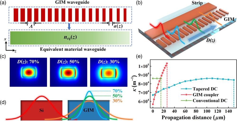
Fig. 1. Planar-metamaterial-enabled refractive-index-distribution manipulation and GIM-enabled adiabatic coupling. (a) Conceptional illustration of a 1D metamaterial structure with a linearly decreasing duty cycle
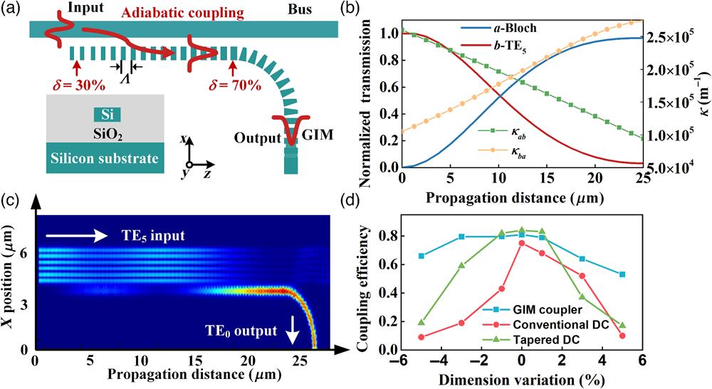
Fig. 2. GIM-based coupler for 16-channel MDM. (a) Schematic configuration of the GIM-based coupler designed for selective mode coupling. The duty cycle of the GIM waveguide
Fig. 3. GIM-based couplers for 16-channel MDM. (a) Schematic configuration of the 16-channel mode MUX. (b) Microscope image and (c) SEM image of the 16-channel GIM-based mode MUX and deMUX. (d)–(f) Magnified SEM images of the coupling regions.
Fig. 4. (a)–(p) Measured transmission responses of the 16-channel mode deMUX. Each subplot shows the transmission and crosstalk recorded at 16 output ports for a selected input channel.
Fig. 5. High-speed data transmission experiment. (a) Experimental setup for the high-speed transmission experiment of the 16-channel MDM chip. The insets show the photographs of the testing platform and the fiber array-based vertical coupling. (b) Monitored optical spectrum of the recombined signal at the receiver side. (c) Calculated BERs of 40-GBaud 16-QAM signals for 16 modes after MIMO-FFE and MLSD. All channels are below the 15% FEC threshold. (d) Recovered constellations for all the 16 modes.


Set citation alerts for the article
Please enter your email address

© Copyright 2018-2021 | Chinese Laser Press. All Rights Reserved 沪ICP备15018463号-20